I have been reading a lot about the Denon DA-500 dac. It is one of the few dac's with 3 or more inputs. Because i need 3 toslink inputs and the rest of my system is all vintage Denon, i really want this DAC. The sound quality should be decent, but i found a lot of info here on modding this DAC. Most threads are very old, and not all the info is complete enought for me to understand, so i tought i would start a new thread. Im a bit of a noob in this stuff, but i build other electronics before, and i get most the basics.
Killing the clock
In this thread im reading about stopping a clock has a bad infuence on the dac's sound quality. This clock is not used for the actual DA decoding. Its only there to support the DAC detecting the right signal. After that signal has been locked the clock is not needed anymore and only couses noise. The thread sugests that its possible to "kill" the clock and improving the sound quality.
There is a simple schematic in the thread that shows how to build the mod. The way i understand it, i have to use a cap, a resistor, a transistor and a diode that have to be connected to the ciruit that is already there creating this:
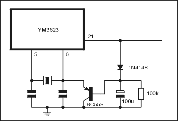
This will somhow stop the clock i gues? But are there any effects on the way the dac works? After powering up the dac and with my PC, PS3 or DTV decoder (all connected trough TOSLink) will i still be able trough switch the inputs on the dac, and stuff like that? Or will the clock remain dead and not allow switching inputs because the dac cant lock on to the signal?
Changing OpAmps
I also read a lot about swapping the opamps for other ones. With a budget for something like max 75$ in opamps what would be the best choice for the opamps? and i gues there is more than 1 opamp, so which ones shoudl i change. Also if i change the opamps do i need to chnage other things too, or can i just swap them?
The power suply
I really think the PSU makes a huge diffrence in audio equipment and from what i am reading there is enough room for improvement in the DA-500. I found some very cheap toroidal transformers i could use to build a whole new PSU with a nice overkill in caps. I could use 2 diffrent transormers for the 12v and the 5V part. As far as i can see from the pictures there is room enough and the cost would be around 25$ so if it would help its a very simple and cheap mod to make. Or would it be better to change the PSU as they did in this thread?
When rebuilding the PSU are there any special things i can do to make it as good as possible?
Bypass caps?
This post show 2 caps installed somehere on the PCB. What do these do, and should i place them too?
Interior mods
In mods of other dacs i have seen some pictures there they placed a metal wall between the PSU and the rest of the electronics. I gues this maybe would lower any noise of the PSU. I also saw some pictures that of modded dac that had copper foil on the inside. Again for the same reason i gues. Do things like these realy help, or are they a waste of time?
Any other mods i can make?
All of these mods should help a lot, but are there any others i should take a look at? maybe replacing some other parts with better ones?
I know these are a lot of questions, but i would really appreciate some help here! Im a noob but i wanna learn!
Killing the clock
In this thread im reading about stopping a clock has a bad infuence on the dac's sound quality. This clock is not used for the actual DA decoding. Its only there to support the DAC detecting the right signal. After that signal has been locked the clock is not needed anymore and only couses noise. The thread sugests that its possible to "kill" the clock and improving the sound quality.
There is a simple schematic in the thread that shows how to build the mod. The way i understand it, i have to use a cap, a resistor, a transistor and a diode that have to be connected to the ciruit that is already there creating this:
This will somhow stop the clock i gues? But are there any effects on the way the dac works? After powering up the dac and with my PC, PS3 or DTV decoder (all connected trough TOSLink) will i still be able trough switch the inputs on the dac, and stuff like that? Or will the clock remain dead and not allow switching inputs because the dac cant lock on to the signal?
Changing OpAmps
I also read a lot about swapping the opamps for other ones. With a budget for something like max 75$ in opamps what would be the best choice for the opamps? and i gues there is more than 1 opamp, so which ones shoudl i change. Also if i change the opamps do i need to chnage other things too, or can i just swap them?
The power suply
I really think the PSU makes a huge diffrence in audio equipment and from what i am reading there is enough room for improvement in the DA-500. I found some very cheap toroidal transformers i could use to build a whole new PSU with a nice overkill in caps. I could use 2 diffrent transormers for the 12v and the 5V part. As far as i can see from the pictures there is room enough and the cost would be around 25$ so if it would help its a very simple and cheap mod to make. Or would it be better to change the PSU as they did in this thread?
When rebuilding the PSU are there any special things i can do to make it as good as possible?
Bypass caps?
This post show 2 caps installed somehere on the PCB. What do these do, and should i place them too?
Interior mods
In mods of other dacs i have seen some pictures there they placed a metal wall between the PSU and the rest of the electronics. I gues this maybe would lower any noise of the PSU. I also saw some pictures that of modded dac that had copper foil on the inside. Again for the same reason i gues. Do things like these realy help, or are they a waste of time?
Any other mods i can make?
All of these mods should help a lot, but are there any others i should take a look at? maybe replacing some other parts with better ones?
I know these are a lot of questions, but i would really appreciate some help here! Im a noob but i wanna learn!
I can't answer all your questions but just some thoughts...
That mod... what the circuit does is hold pin 6 low (100uf cap turns on transistor) for an ideterminate time at switch on until cap charges via C-B junction. If pin 21 goes high or is high then the transistor is off and the osc runs.
Without knowing exactly how it all works, stopping an osc like that doesn't seem a smart move... it can cause lockups etc in logic devices. As I say though, without knowing exactly how it all works etc, it's impossible to say. The action of the transistor means the osc starts unpredictably too... not cleanly.
PSU... personally 🙂 I would leave alone and perhaps look to (and measure) any rails and see how clean they all are. Adding an external PSU while OK in theory, might in practice be worse... thinking wiring, secondary leads radiating noise (caused by rectifier commutation) etc etc.
I would look to replacing caps with high quality low ESR types for the reservoir and local decoupling. Is there suppresion over the bridge/s rectifiers. Perhaps add 0.1 or 0.047uf surface mount caps on the print side between electroylitic legs if they have 5mm pitch or 2.5mm pitch etc.
Opamps... again, to be sure you need to see the circuit. Bipolar or FET. Is DC offset likely to be a problem. Are they single opamps ? do they make use of the DC null pins, as different opamps use different arrangements (and even pins, 1, 5 and 8)
Opamp decoupling... adding a small (0.1uf) cap directly accross the supply pins is beneficial. Never (as a general rule) decouple supply to ground as that introduces rail disturbance into critical signal grounds.
Those two caps look to be near 8 pin I/C's (opamps)... again look at the circuit.
For decoupling... use an oscilloscope, correctly grounded and correctly grounded to the relevant point you are looking at and measure 🙂
Thanks for your reply. That kill the clock mod seems to be a popular mod here, and people say it really makes a diffrence (more info). So im sure it works. I just want to know if there are any side effects in controling the dac. I dont have any schematics of the dac, so i cant see how everything exactly works yet.
In the same tread im writing about (and in others) i can read the the PSU really has a few faults in its design and that a few small mods really help. Im doing those small mods for sure, im just wondering if a whole new PSU with a overkill in caps, toroidal transformers and schottky rectifier.
The opamps are a double opamps as far as i know, so they dont have the offset connections. When browsing ebay i did see some converting solutions where 2 single opmamps in smd where mounted on a dip socked to work as 1 double opamp, so maybe it possible to place any omamp in this dac
I would want to see the circuit details before hacking it about 🙂 that applies even for the opamps really.
Are they FET or Bipolar... if they are FET and the circuitry is high impedance with unmatched impedances then a Bipolar opamp may not work well.
If you are set on modifying it then fair enough... just be aware.
Are they FET or Bipolar... if they are FET and the circuitry is high impedance with unmatched impedances then a Bipolar opamp may not work well.
If you are set on modifying it then fair enough... just be aware.
I have been hearing a lot that this dac is good but isnt perfect, and i would be better of looking for another DAC. I do want this dac tho. Its one of the few dac with multiple inputs, and its pretty simple to work on. I also like the fact that is denon (like the rest of my equipment). For now i am sticking with this one. Its will be my first DAC i will mod. When i get bored with this one, i will move on to another one.
Anyway, i will be recieving the denon tomorow, i also ordere some parts for the PSU.
I finaly was able to buy service manual somewhere. You can download it here:
MEGAUPLOAD - The leading online storage and file delivery service (datasheets of the analog stage IC's are included)
The schematics are pretty easy.
So this thing uses 4 dual opamps. 2 for every chanal. 1 is used for I/V and buffer, and one is used for filtering. I have been reading some stuff about opamps, but cant really find what opamps i should use. I have been reading very good things about Burson Audio discrete opamps. They are not very cheap but according to some reviewa are very, very good. I was thinking i could replace the PC4570's with these burson's, and the opamps in the filters with something cheaper. Any opinions?
I'll have a proper look later... the 5218 looks to be used as a "gyrator"
Are the opamps in your DAC 8pin DIL types or are any SIL types... they were available in both types.
Are the opamps in your DAC 8pin DIL types or are any SIL types... they were available in both types.
From the PCB layout they look to DIL so you have loads of choice. For the 4570 I would try a good FET opamp. One I have used very sucessfully is the OPA2604... it's one of the most "analogue" sounding devices I have heard used as an I/V convertor. For the 5218... well you could use a OPA2604 here too. The LM4562 is bipolar, but held in high regard by many.
Edit... No experience of Burson, and have heard good and bad reports.
Edit... No experience of Burson, and have heard good and bad reports.
The OpAmps are DIP.
I kinda feel like trying the OPA2604 as a replacement for the 5218's and the Burson Discrete OpAmp for the PC4570. I like the idea of not having to many chips in the analog stage. I have been reading good things about the burson stuff, so why not try it? I do think they are a bit to expencive to also use as a replacement for the M5218. I can get the OPA2604 for as low as 6 euro. The bursons will cost me just over 50 euro per unit, so they are 10x as expencive as the OPA2604 😛 Oh well, its fun to try i gues!
If i am going to replace the opamps should i also replace the resistors and the caps around them for something of simular quality? If so, what should i look for?
I also saw some stuff on ebay where 2 single opamps like the OPA627 are converted to 1 dual opamp. (The item on ebay) Is this any good, or would a OPA2604 be the same?
The OPA627 is a high speed device and needs to be implemented correctly. If fitting on adapters you [may] run into stability issues. With anything like this you need to use a 'scope to check.
The OPA2604 should be fine as a drop in replacement. Ultimately how any device "sounds" depends on the exact circuit configuration and interaction with all around it... you are going to have to try them and see.
Changing resistors will have zero effect IMO here.
Caps... you could perhaps usefully change the electroylitics around the DAC for low ESR types... that fit properly 🙂 and also the output coupling cap, but that's about it.
Im also not to sure about those single-dual opamps conversions. I wonder what happens if you leave all those offsets disconnected. I gues strange things can happen.
I gues im going with that OPA2604 as a replacement for the 5218's and the Burson discrete's as a replacement for PC4570. I just hope that the opa2604 are not going to be the weaker link in the chain that will effect the Bursons preformance.
I am going to change those caps for sure. Just thought maybe the quality of the resistores would have a effect too.
No problem leaving offset pins disconnected. The problem is using high speed devices and having problems with stray capacitance and inductance causing instability.
Why not fit sockets and try experimenting a bit. Use your OPA2604 to replace the 4570 and even put the removed 4570 where the 5218 is.
And for a bit of fun... try the TL072 for both... it's a surprisingly capable performer and costs peanuts... honest 🙂
And listen carefully... don't be to hasty dismissing anything or thinking one is better than the other. Listen long and hard. If it doesn't sound "good" come back to it a few hours later... your expectations play a bigger part in all this than you may think.
i got the dac and my new transfromers today. I think im ordering the other parts in thenext few days. Just a small question about the PSU.
I see some very complicated psu's being used in dacs. Are there any special designs that i should look at? or will a simple 7812,7912,7805,7905 a few big caps and some schotkyy's for the rectifier do?
I see some very complicated psu's being used in dacs. Are there any special designs that i should look at? or will a simple 7812,7912,7805,7905 a few big caps and some schotkyy's for the rectifier do?
It's not that easy 🙂 PSU design and implementation is a vast subject. Correct grounding and points of reference are vital.
As an example, you design a perfect PSU with zero noise etc. Feed it into a few cm of wire or PCB print and measure the noise at the component being fed and it's not so good. Why... because the resistance and inductance of the wire/print are significant and cause the noise to appear. Measure at the PSU end and it's still "perfect". That's not being fussy... you can actually see the noise etc increase just "sliding" an oscilloscope probe up and down a piece of print or even up and down a few mm of "leg" on a capacitor. The ideal solution is regulation right at the component you are feeding.
As an example, you design a perfect PSU with zero noise etc. Feed it into a few cm of wire or PCB print and measure the noise at the component being fed and it's not so good. Why... because the resistance and inductance of the wire/print are significant and cause the noise to appear. Measure at the PSU end and it's still "perfect". That's not being fussy... you can actually see the noise etc increase just "sliding" an oscilloscope probe up and down a piece of print or even up and down a few mm of "leg" on a capacitor. The ideal solution is regulation right at the component you are feeding.
i understand that, and it will never be possible to make a perfect psu. I was just wondering if it would be smart to make a better psu than just a regular 78xx
Many will say yes... as ever it's how you carry that to the application in question.
Have a read at all this and look at the picture from post 53 on,
http://www.diyaudio.com/forums/power-supplies/126929-low-cost-regulator-between-jung-flea-3.html
that will keep you entertained 😉
Have a read at all this and look at the picture from post 53 on,
http://www.diyaudio.com/forums/power-supplies/126929-low-cost-regulator-between-jung-flea-3.html
that will keep you entertained 😉
I have read the whole thread. To behonest i dont understand everything, but most i do get. Basicly the idea is that the psu will will not have a stable outpu voltage when current is drawn in a peak. This offcouse will happen with any psu, but a normal lm317 or 78xx will have bigger volage drops/peaks than a more advanced cirquit will have so that means less noise.
I cant find a final ciruit in that thread tho and as far is i can read noone ever build a final model. So if i would want to use the schematic out of that thread i would have to do a lot of testing and everything first. Right now i am not looking for that. Im looking for a (almost) ready PSU design that peforms better than the 7812 that is simple to build.
After looking a bit more at the schematics and the parts i am planning to use, i now have the folowing ideas:
I have 2 toroidal transformers of 2x12V and 30VA
The whole analog part of the DAC actualy has its own power lines and it looks very simple to connect the opamps to a single psu. I gues this is where a good psu reall can make a diffrence. Also i read that the Burson discrete opamps preform even better with a higher voltage (more than 12V) By giving the analog part its own PSU i could also boost the voltage a bit. the OPA2604 will work at 24V so something like 15-18V should not hurt the preformace of any parts, and probbaly help the burson's a bit. Ofcourse the current drawn by these opamps is very low, so 30Va should be enough 😛 A nice bridge, a 7815, 7915 and a few big low esr caps should be able to power it. Or would it be smarter to build something more advanced as a PSU for the opamps.
Im not sure what i should do with the rest of the PSU. maybe only replace the transformer and replace the caps for low esr types. I gues the digital parts dont need anything very special. But the digital part also powers the PCM1702's and actualy build the analog sound ofcourse. Should i do anything special here?
Any advice would be very welcome again!
A 12-0-12 transformer will give around 17-0-17 Vdc after rectifying so on that basis you are limited to 12 volt regs allowing for reasonable headroom. You are going to run into all sorts of complications trying to use two transformers... yes you could get 34-0-34 vdc... the OPA2604 will work at a lot more than 24 volts, and is one of the few devices to be rated at 24-0-24 (48volt) max supply. as against the normal 15-0-15.
OK honest opinion... and I know you want to experiment... but my advice is tweak what is there. Change the opamps, listen, learn, listen some more... look at adding local decoupling directly across the supply pins to the opamps (not to ground), and look to replacing any small electroylitics with high quality low ESR types. Perhaps add a 0.01uf to 0.1uf surface mount cap across all these electroylitics if they have a 2.5mm lead pitch. The caps fits directly on the print between the legs of the electro.
Big caps bring there own problems... they alter the conduction angle of the bridge rectifier, mean that the current "spikes" that top off the caps each half cycle are much larger (because the cap is bigger so the voltage across it falls less each half cycle). The energy drawn by the circuit remains the same so the charge pulses are correspondingly larger... causing the transformer to perhaps run hotter because of iron (magnetic) losses in the core, and perhaps to "radiate" more in the way of interernece due to the larger currents that flow.
Everything is a compromise unless you go all out to redesign from the ground up 🙂
So I would just keep things simple and I think you will see the biggest result from just swapping the opamps.
I could use a 7815 or a lm317 for 15v, but if i need a higher voltage i know a where to get some high quiality stuf for a a few euro so needing a higher voltage psu would not stop me.
But i understand what you saying with trying first. Its just that i heard a couple of times that the psu on this one isnt that great. From what i have seen in high end audio stuff is pretty common to use a seperate transformer for digital and analog.
Forgive me for the newbie questions, but what problems would 2 trasformers give? Is there really somehing agaisn doing this?
Is placing a cap over the supply pins of a opamp always a good idea? Or will it actualy make the signal worse in some cases. What value should i use? 1uf? or lower? I gues i understand what a cap would do there, but not enough to know the right value.
Also can you please explain what the small smd caps do when you combine them with a bigger one? And how i choose the right value when adding them?
The psu caps should not be to big ofcourse, but when the transformer or the bridge isnt running hot it cant hurt much neither right? And if i instal a toroidal transformer there cant be very much noise right?
But i will take your advice and change the opamps and caps first before try anything with building a whole new psu.
I have had the DAC connected for a day now. I like it so far. I have it connected trough my sony DSP (SDP-D905) that i used as dac before. This way i can compare them good and connect/disconnect very easy. The sony might add a small amount of jitter, but its good for now. The denon has a clearer sound than the sony, so its already a improvement. The only thing i dont like for now is that it takes the dac some time to lock on the signal. I use it many hours every day playing FLAC and MP3 from my PC, and the way my soundcard (or windows) works makes that between 2 songs the S/PDIF connection is stoped and rebuild again. It takes the dac 1-2 seconds to lock the signal, so i miss the first 1-2 seconds of the song. I gues i will be able to fix this some way.
anyway, im pretty happy, and cant wait to tweak it! I attached some pictures
anyway, im pretty happy, and cant wait to tweak it! I attached some pictures
Attachments
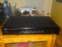
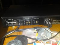
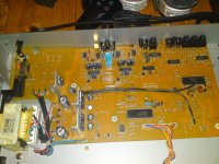
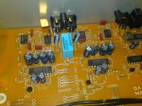
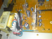
Thanks for the pictures.
Two transformers create problems with you getting the supplies to the PCB in a way that isn't going to degrade performance. Phase of the windings ?
The -/+12 volts doesn't just feed the opamps if you study the circuit... other changes have to be made to.
If you start fitting different sized caps (more uF) although unlikely, you can create a situation in logic circuits called a "race hazard". What that means is that the circuit may take into account the rise times of the supply as you switch on. If one rail is delayed (due to bigger caps charging) it can confuse the logic and cause a latch up. Unlikely but not unheard of.
All electroylitics have a tendency for "xc" capacitive reactance to increase past a certain frequency. You expect the cap to become more of a "short" as frequency goes up but it doesn't because of self inductance of the leads and physical construction of the cap itself.
A real cap, is a capacitor in series with some self inductance and a little resistance. Adding a smaller cap across it negates that effect somewhat. And to take things even further you can add a 0.1uf in series with say a 1 ohm across supply. It's all a matter of identifying what frequencies you are working with and how to get the best result.
What is wrong with the original PSU ?
- Status
- Not open for further replies.
- Home
- Source & Line
- Digital Source
- Modding a Denon da-500. This noob needs some advice.