Since I've got a bunch of AMP3s all built except for the output inductors, and I had a few spare toroids and lengths of wire laying around, I decided to experiment! A little while back I posted a thread about the use of differential output inductors in the filter section of a class d amp. There were only a few responses but they basically told me it's been done before. Well I wanted to see what it sounds like with a Tripath based amp.
Attachments
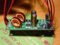
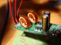
I used the same core and wire as supplied with the AMP3 kits. As you can see there are two windings on one core - both of the inductors for one channel are on the same core. Both windings are 39 turns, 20 on the bottom and 19 over top and between the bottom turns. You may be able to squeeze one more turn of wire but that's pretty much the limit with the kit supplies.
Attachments
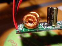
Winding them was time consuming but I did it as neatly as equally as possible between both windings on the same core. I wanted to mount them laying flat but it was an awkward position for them, so I stood them up. A little more work winding but it sure looks pretty cool!
So how does it sound? Well, this amp isn't broken in yet, and I haven't soldered input caps on so I can change out the caps to audition different one. But for having the Pana FC electrolytics and no break in time it sounds and images close to that of my fully broken in amp3. Hopefully that means it'll sound better after a nice break in!
So how does it sound? Well, this amp isn't broken in yet, and I haven't soldered input caps on so I can change out the caps to audition different one. But for having the Pana FC electrolytics and no break in time it sounds and images close to that of my fully broken in amp3. Hopefully that means it'll sound better after a nice break in!
Attachments
Slick work there Brian! Maybe I need to get you some of my type 61 cores. Need only 11 turns for 10uH. Much easier to wind. I've been thinking about doing coils like that too. Glad to see you've done it.
Did you check to see if there is less RF at the output?
--Of course, reading one of the other threads on this forum, maybe less RF is not good. 😉 --
Did you check to see if there is less RF at the output?
--Of course, reading one of the other threads on this forum, maybe less RF is not good. 😉 --
Thanks Michael!
I haven't checked to see if there's less RF on the outputs (yeah, less RF isn't necessarily 'more' for some folks 🙂 ). My gut feeling tells me that there probably is because I'm willing to bet the inductance of each winding is less than 10uH, which will both raise the cutoff frequency and the Q of the filter. It doesn't sound worse than a regular amp3 though. I have to get this one hooked up to my cd player and broken in for a better comparison.
I haven't checked to see if there's less RF on the outputs (yeah, less RF isn't necessarily 'more' for some folks 🙂 ). My gut feeling tells me that there probably is because I'm willing to bet the inductance of each winding is less than 10uH, which will both raise the cutoff frequency and the Q of the filter. It doesn't sound worse than a regular amp3 though. I have to get this one hooked up to my cd player and broken in for a better comparison.
If you overlaped the two different windings would turn the torroid in to a 1:1 transformter of sorts, causing problems between channels?
In other word does those choke work simply because they windings are separated on the core? I wonder if there is any interelation because of them being on the same core. Bottom line how they sound is the primary concernd. I guess what I am saying is what advantages and disadvantages theoretically exist with this type of choke arrangement.
Terry
Winding it like a 1:1 transformer with the windings right next to each other over the entire core shouldn't cause any problems. I did it the way I did for two reasons. The main reason is to electrically isolate the inductors in case of some sort of short. The second was that I wanted the two windings to be as similar as possible, although now that I think about it some more they would be identical if you wound it the way you mentioned. All the wires would be positioned at one spot too. Maybe that will be something to try with the remaining two inductors 🙂
These chokes work because their magnetic fields are linked through a common core, kind of like how two resistors in series carry the same current. If both of the output inductors in the output filter of an H bridge are forced to share the same magnetic field and they have exactly the same number of windings, then the windings should theoretically carry exactly the same current. Inductors with separate cores, however, can have different currents flow through their windings. How much of a difference this makes with the performance of class d amps, I don't know. As for their use in the amp3, the differences seem to be minimal so far but the amp does not sound worse than the standard configuration.
If you wanted to mass produce these guys you could cut down parts to two cores instead of four and save costs 😀
Why not used a torroid core whose diameter is the same as the amp three and wind all four chokes on it. Now that would save expense. You could wind them one of three ways the way I see it. Aside from that will using better caps on the output influence anything? The audio signal doesn't flow through them to the speaker, but could their perfomance effect the signal path through the speaker?
Terry🙂
Terry🙂
You can use one core for both inductors of a bridged output (one channel) because of the fact that they should have the same current going through them in opposing directions at all times - it's important that you pay attention to current flow through the windings because both windings have to have their flux flow the same direction otherwise it won't work. You can't use one core for both channels because each channel has a different signal and thus different currents through the output inductors on each channel. If you wound all four inductors on one core I can't imagine you'd have good imaging or good sound at all. The output devices certainly wouldn't enjoy that!
Better filter caps could influence things. Caps that have their lowest impedance right at the switching frequency (for fixed modulation frequency amps) would be the best for use in the output filter. They would most likely influence the sound as they play a large part in filtering out the switching frequency even though they aren't directly inline with the driver.
Better filter caps could influence things. Caps that have their lowest impedance right at the switching frequency (for fixed modulation frequency amps) would be the best for use in the output filter. They would most likely influence the sound as they play a large part in filtering out the switching frequency even though they aren't directly inline with the driver.
I read somewhere that common mode chokes (same core) don't saturate because of the opposing currents. Seems hard to believe. Anyone know?
Well the core shouldn't saturate unless there is an extreme amount of common mode noise. The way they're wound causes the flux of the two windings to oppose each other and effectively cancel out when current is flowing in opposite directions through the windings.
Have a look at page 27 of this pdf for a picture of how a common mode choke is wound:
http://www.murata.com/emc/knowhow/pdfs/te04ea-1/26to28e.pdf
Have a look at page 27 of this pdf for a picture of how a common mode choke is wound:
http://www.murata.com/emc/knowhow/pdfs/te04ea-1/26to28e.pdf
You went a step beyond what that pdf file says to do didn't ya? I mean they don't show having each winding wind back over itself. I wonder what if anything that does, kind of confuses those little iron molecules doesn't it, field going all different which ways all at the same time. You must love torchuring them, because they can't know which way is north (pardon the pun, but I couldn't resist) with the way you wound them coils. If you had a larger core could try winding them exactly the way the pdf file instructs.
TG🙂
P.S. I was expecting at least 27 pages of interesting reading, that file only has three pages in my web browser.
TG🙂
P.S. I was expecting at least 27 pages of interesting reading, that file only has three pages in my web browser.
Yeah, I'm all about overkill 😀 Seriously though, I overlapped the windings to get more inductance. I didn't wind the inductors the way the pdf shows because they wouldn't work properly if you did. One winding is like the one on the bottom half of the core and the other winding starts on the right side on the top. That's a bad description so just picture the bottom winding rotated 180 degrees counterclockwise about the center of the core on the top half of the core.
Sorry to disappoint with only 3 pages of interesting reading
Sorry to disappoint with only 3 pages of interesting reading
An externally hosted image should be here but it was not working when we last tested it.
Thanks for the link, Brian. Reading that really makes the common mode choke seem like the way to go for the bridged amps.
Why? What are we trying to get rid of? The swtiching current, which is common to both legs. What are we NOT trying to get rid of? The audio signal, which is not common, but opposite. Sounds like a winner. Might be able to use smaller inductances, too.
The only "uncommon" signal that might be more present would be the slight differences in the two switches. A normal choke would filter those out. Maybe a common mode would not. It's worth a look!
We're making good progress.
- Status
- Not open for further replies.
- Home
- Amplifiers
- Class D
- Modded AMP3 output filter