Until those tranfo come in, will it be fine to start altering capacitor size on the cathode bypass (~30uf) and the dc blocking cap (1 - 2.2uf) without worry?
If the size of the cathode and blocking cap determine the bass cutoff, what determines the treble?
Now have a little hum independent of volume setting, hoping that goes away when removing the extra long leads to the blocking caps.
If the size of the cathode and blocking cap determine the bass cutoff, what determines the treble?
Now have a little hum independent of volume setting, hoping that goes away when removing the extra long leads to the blocking caps.
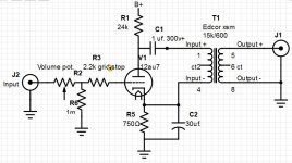
I think you could go to 220uF or 330uF, at least that's where I would start. This will bring the gain up, which you don't really want, but it will also drive down the output impedance of the preamp, which you definitely want. That extra gain will be quickly tossed out by the transformers anyway.
The 2.2uF coupling caps should have been in there from the start!
The cathode bypass cap does not determine the bass cutoff. You can have no cap at all and have perfectly flat frequency response.
The coupling cap and the load impedance being driven by the preamp tends to be what limits LF response.
The 2.2uF coupling caps should have been in there from the start!
The cathode bypass cap does not determine the bass cutoff. You can have no cap at all and have perfectly flat frequency response.
The coupling cap and the load impedance being driven by the preamp tends to be what limits LF response.
@audiowize after what must have been over 100 pages of reading posts I came across this. The original designer of the 4Suniversal pre decided the impedance of the 4S was too high for most SS amps and designed a cathode follower for it. Other than values, it's very similar to what you drew up.
I noticed the original designer (Suncalc at diyaudioprojectsdotcom) kept the 'universal' concept but I assume you optimized the design solely for the 12au7 in both positions in post #8?
Thread is posted with diagram in post #2; DIY Audio Projects Forum • 4S Tube Preamp with 12AU7 Cathode-Follower Output Stage
Last edited:
I'm not registered for that website, so I can't see his design.
A 12AX7 is only rated to run about 1mA of current, so that will seriously limit cathode follower performance if you decide that your cathode follower needs to work with 12AX7s.
A 12AX7 is only rated to run about 1mA of current, so that will seriously limit cathode follower performance if you decide that your cathode follower needs to work with 12AX7s.
Last edited:
My apologies. I was reluctant to cross post the diagram in fears of sharing something that someone might not have wanted shared on another forum. Just to give credit where credit is due, this diagram is from Suncalc at diyaudioprojectsdotcom. If someone doesn't want it posted here, I will remove it.
Shared album - k mier - Google Photos
Shared album - k mier - Google Photos
Last edited:
Yeah, that is designed to let a 12AX7 work, which is a waste of time in my opinion.
Not directly coupling the circuit also seems wasteful.
Not directly coupling the circuit also seems wasteful.
Adding the cathode follower, will demand on the power supply be increased and will this need to be addressed?
Yes. In the case of the design you linked to, there's not a lot of DC current being drawn at all, but if you design for the beefier tubes, then this starts to matter a lot more.
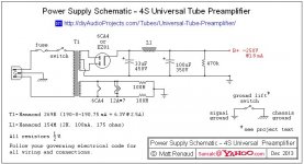
Though I might be able to build it with parts on hand but no. Do have some rather expensive 22.5k and 750Ω wirewound 11-12 watt resistors. Can they be subbed for R4 (47k) and R3(820Ω)?
This is the power supply and I used the Hammond 269e 190-0-190 .75ma, +6.3v@2.5a How much will this need to be modified or is it even suitable? This came from diyaudioprojectsdotcom giving credit. If I cannot get this power supply to work I may as well just leave this pre as is and move on to something else. And no, I never got around to ordering the output transformers.
This is the power supply and I used the Hammond 269e 190-0-190 .75ma, +6.3v@2.5a How much will this need to be modified or is it even suitable? This came from diyaudioprojectsdotcom giving credit. If I cannot get this power supply to work I may as well just leave this pre as is and move on to something else. And no, I never got around to ordering the output transformers.
Attachments
@audiowize In post #8, where does the volume pot go and what resistance is required? Getting a parts list together.
- Home
- Amplifiers
- Tubes / Valves
- Modded 4s Universal pre