Hello Everyone,
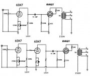
I have a SE 6SN7 - 6V6 amp (boozhound Labs) that works very well as it is, but now I would like to get a little more out of it. I reworked the schematic as to how I think it should be changed (just guessing) but choosing the values is well beyound me. Would anyone like to make suggestions for the missing values and comment on the changes? I already have a push/pull amp so I dont want to go there, and I want to keep the mod as simple as possible. My power supply can handle the extra tube just fine.
I have a SE 6SN7 - 6V6 amp (boozhound Labs) that works very well as it is, but now I would like to get a little more out of it. I reworked the schematic as to how I think it should be changed (just guessing) but choosing the values is well beyound me. Would anyone like to make suggestions for the missing values and comment on the changes? I already have a push/pull amp so I dont want to go there, and I want to keep the mod as simple as possible. My power supply can handle the extra tube just fine.
Attachments
what is it currently delivering for you that you like?
what little more are you wanting to get out of it?
what little more are you wanting to get out of it?
I'm assuming that the second (lower) schematic is yours?
If so this will just add a lot additional gain and probably reduce resolution in so doing. It's not an improvement in any meaningful sense that I can see..
At the minimum a cathode bypass cap on the output stage would be a good idea..(existing design) A 100uF/35V part should suffice..
Selecting a hotter operating point in the first stage and implementing fixed bias in the second stage might bring some improvement as would the fitting of a higher quality OPT.
I reinterpreted an old 6J7/6V6 all pentode design about a year ago (here on diyAudio) and used a small 12V camera battery to provide grid bias to the output stage..
More than likely you need to build a more powerful amp to achieve the improvement you are looking for. Check out tubelab's simple single ended amplifier. Great project and learning opportunity and at the end of it all a good, solid amplifier.
I'm using a CD player (Pioneer) from the 70's or 80's. I have not measured it's output but I think it's less than 1 volt. I also have 12 inch, three way speakers from that same era. I get good sound and volume from that setup but I would like a little bit more volume (power). I already have a 6V6 push/pull and a 6BQ5 push/pull, so I dont want to build a whole new amp, just improve this one if I can.
I'm using a CD player (Pioneer) from the 70's or 80's. I have not measured it's output but I think it's less than 1 volt. I also have 12 inch, three way speakers from that same era. I get good sound and volume from that setup but I would like a little bit more volume (power). I already have a 6V6 push/pull and a 6BQ5 push/pull, so I dont want to build a whole new amp, just improve this one if I can.
Post 1983 as that is when CD was introduced.. Standard is 2Vrms.. You just need a more powerful amplifier or more efficient speakers I would guess, the gain is probably more sufficient to drive the power stage to full output.. A 6V6 is good for about 1.5W in triode IMLE, and about 5W in pentode. Do you hear obvious clipping on loud music as things now stand? - If not then additional gain might be what you need, otherwise not..
Like my equipment (except amp) I am old (67 years old) and just damn glad I can hear the thing play. I can turn full volumn and not hear clipping and it's almost uncomfortable to be near. I would not listen at that level for long, if at all. Except to hear what it can do. I'm not prepaired to do any meaningful testing, just listening to it. I'm retired and just amusing myself with this stuff.
Totally cool.. Take a look and see if there is a bypass capacitor on the cathode resistor of the 6V6 - if not present installing one will give you a little more gain, and better bass performance. Possibly even better would be battery derived grid bias.. (Measure the voltage across the cathode resistor and then figure out if you can get there with some combination of available batteries.. 1.5V, 9V, 12V alkalines) The grid bias gets rid of the cathode bias cap and resistor..
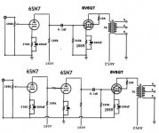
I built this amp about 6 months ago. Yes, there is a bypass capacitor on the cathode resistor of the 6V6. I forgot to add it to the schematic after I built the amp. This design is from Boozhound Labs. My other two amps (6V6 PP and 6BQ5 PP) could blow the walls down if I turn them up using the same CD player and speakers. I have a set-up where I can choose which amp gets switched onto the CD and Speakers so I can listen to anyone whenever I want to. My gut feeling is that the amp could put out "just a little more" if I would drive the drivers just a little more. Updated schematic.....
Attachments
just a little more (in the context of keeping this topology and these parts) is not going to make an appreciable difference in the power you hear.
There are some simple things you could do to fettle the amp - I'd go with a LED bias on the 6SN7 and a LM317 under the 6V6 as a start.
There are some simple things you could do to fettle the amp - I'd go with a LED bias on the 6SN7 and a LM317 under the 6V6 as a start.
The lower of the two schemos should blow up. You've got over 100 volts positive on the grid of the 2nd tube... That would turn the tube on all the way times 100, and possibly cause arcing inside the tube. The grid would act as a plate and possibly glow red, but it might be hard to see since it's inside the plate housing.I built this amp about 6 months ago. Yes, there is a bypass capacitor on the cathode resistor of the 6V6. I forgot to add it to the schematic after I built the amp. This design is from Boozhound Labs. My other two amps (6V6 PP and 6BQ5 PP) could blow the walls down if I turn them up using the same CD player and speakers. I have a set-up where I can choose which amp gets switched onto the CD and Speakers so I can listen to anyone whenever I want to. My gut feeling is that the amp could put out "just a little more" if I would drive the drivers just a little more. Updated schematic.....
You need to put a coupling cap there (plate of 1st tube to grid of second tube)(0.02uF 400V should be fine), and then put a 1-2k 1/2 W resistor from the cathode of the second tube to gnd (sets the bias level) (don't waste your time with LED bias - it's a wild card). You can bypass this resistor to gnd with a 25uF 100V cap for more gain still, or if there's too much gain at that point, you can cut out the bypass cap across the cathode resistor of the 1st stage (should also be a 25uF cap unless you want to do some frequency response adjusting). The grid of the 2nd stage also needs a 250K - 1M 1/2 W resistor (value not critical) to gnd. At that point you should have plenty of gain. I'd actually put the volume control after the first stage (1Mohm Audio Taper) in place of the R to ground off the grid of the 2nd stage), so hiss and hum noise goes down better when the Volume is turned down. Replace the input pot with a 1M 1/2W resistor to gnd, and put a 10K-50K resistor in series with the grid after the 1M to gnd. Hope this makes sense. Feel free to ask for further clarification or reasons why. I've designed and built many guitar amps in the last 8 or so years.
Last edited:
Thanks aardvarkash10 . I will research the 2 suggestions.
It will not make it any louder. mind you.
Thanks Humdinger for your reply. I chose this topology after reading this article....
Boozhound Laboratories
Please read it and let me know where I went wrong.
The original circuit comes from here....
Boozhound Laboratories
Again, thanks to all who replied
Boozhound Laboratories
Please read it and let me know where I went wrong.
The original circuit comes from here....
Boozhound Laboratories
Again, thanks to all who replied
I would recommend you explore changing the 6SN7 to a 6SL7 if you want more gain before the 6V6 output stage. This is by far the easiest way to do that "experiment".
see your own referenced website here for the schematics using the 6SL7
Boozhound Laboratories
You are likely already aware that the octal 6SL7 is directly pin compatible with the 6SN7, but I mention it in case you are not. You will need to modify the 6SN7 cathode resistor, easiest way is to add another one of the same value in parallel (2700 ohms now, 2 in || would be 1350, close enough to 1400 ohms needed.)
Bob
Last edited:
I think that the easiest way to get more power from one 6V6 is to pentode-connect it instead of triode as it is now. Supply voltage could be also a little higher, some 300 V for example.
If the driver stage will be chaned to 6SL7, then there will be sufficient amount of gain to apply global negative feedback and get a quite good linearity and low distortion.
If the driver stage will be chaned to 6SL7, then there will be sufficient amount of gain to apply global negative feedback and get a quite good linearity and low distortion.
Yep, you are now describing the driver and and output stage of the famous Fender Champ circuit that also used a single ended 6V6 with fixed screen in pentode mode. . Of course that one used a 12AX7, and had an extra gain stage for the low level (mV levels) guitar input.
Attachments
Here is a schematic for a 300B SE amp I used as a basis for my 300B build.
2700R for the cathode resistor on a 6SN7 seems very low. As mentioned earlier, I ended up using a red LED which ends up making about 9mA in the front section.
Depending on the amount of current you need for the 6V6 I like the idea of using a CCS on its cathode. The LM317 is a slick little setup. I have mine running about 81mA on an EL84 push pull amp flawlessly. All you have to do is take advantage of the 1.25V differential and use ohms law to get the resistor value you need. Say you want 40mA...R=1.25/.040 = 31.25ohm.
Attachments
I would recommend you explore changing the 6SN7 to a 6SL7
I love the 6SN7 but for some reason I prefer the 6SL7 -6V6 combo. It sounds better to me.
- Status
- Not open for further replies.
- Home
- Amplifiers
- Tubes / Valves
- Mod to SE 6SN7 - 6V6 amp