abq-pete said:
I had only set the master/slave jumper, leaving the rest at their defaults. I unplugged the unit and changed the jumpers that control the audio interface (AIF_CONF). These switch between 16-bit I2S, 24-bit I2S, 24-bit left justified with flags, and 16-bit right justified. After making the correct selection I am now enjoying some very nice music!
How did you set the jumpers?

abq-pete said:Truth be told, I also purchased a 970 for the modification but was very frustrated with trying to find suitable locations to attach the signal wires. It would have been nice if Oppo had placed the same headers on the 970 as I only want the audio portion and not pay for the Faroudja video chipset.
I would also like to remind all you modders that in the first 2 pages of this thread I wrote that I couldn't get the mod to work on the Oppo 970 or Oppo 971. On those models you must solder wires to IC pins on 0.5mm spacing.
That is not a good DIY mod by any means.
abq-pete - sell the 970 on eBay while it's still worth something 😀
Rossl Hi,
I also want to order one of your Oppo 981 mod boards. How should I transfer you the money? Do you still have boards available?
Thanks
Ronenash
I also want to order one of your Oppo 981 mod boards. How should I transfer you the money? Do you still have boards available?
Thanks
Ronenash
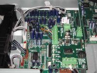
OK. I think I attached a picture (I hope...). Here is a summary of what I did:
1. I mounted the daughter-board to the main-board by removing the front right screw, replacing it with a standoff that came with the daughter-board, and then screwing the daughter-board to the standoff. Looks almost like it was meant to be mounted there!
2. The signal wires are some cat5e bits I had sitting around. I made them appropriately short so that they would just reach the daughter-board. They are soldered into the header on the main-board and screwed to the terminals on the daughter-board.
3. As rossl mentioned, it gets kinda warm in the chassis. As I did not need any video output, I disconnected the HDMI board. As luck would have it, the power cable to HDMI board has 5v on it so I took that to power the daughter-board.
4. As I also do not need the main output board with the audio and video connectors, I removed that as well. I threaded a coax cable through the open chassis holes and connected it to the daughter-board.
5. Of course, before I did any of this work, I updated the firmware, set the SACD/CD priority to SACD 2-Channel, set the DVD-Audio/Video priority to DVD-Audio, and set LPCM to 192K, etc.
Because the manner in which I made the mods, I can remove all trace of the alterations should the unit require servicing.
So far, I have tested 44.1, 48, 88.1 and 96K. My DAC confirms these signals are being sent. I will check 192K as soon as I find the disc with that signal on it (around here somewhere...).
Regards, Peter
Attachments
Russ White said:Very glad you got it working! I hope it fits inside ok.
Cheers!
Russ
Russ,
Using the standoff on the main-board allows the daughter-board to fit perfectly. I was a bit worried about the terminals and considered removing them. Luckily it fits just fine. However there is not chance of stacking the Metronome (ASRC) on the unit. If I choose to go that route, I will have to mount it on the side somewhere...
By the way, thanks for working on this with me.
Regards, Peter
rossl said:
How did you set the jumpers?
rossl,
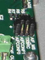
The correct jumper settings are:
AIF_MAS 2-3
TXSRC 1-2
AIFCONF1 1-2
AIFCONF0 2-3
Attached is a close-up.
Regards, Peter
Attachments
rossl said:
I would also like to remind all you modders that in the first 2 pages of this thread I wrote that I couldn't get the mod to work on the Oppo 970 or Oppo 971. On those models you must solder wires to IC pins on 0.5mm spacing.
That is not a good DIY mod by any means.
abq-pete - sell the 970 on eBay while it's still worth something 😀
Actually there really wasn't any mention of the 970. You originally tried it on the 971 (which I also have 🙂 ) but had problems and since it lacked SACD.... The 980 also was considered but pictures revealed that it lacked the header as well. I thought I would give the 970 a chance in hopes that it had the header but alas...
I would have tried harder with the 970 but since that would introduce two variables (970 and Twisted Pear Audio board), I thought it better that I get it working on an easily verifiable platform (981). Now that I have done that, I may revisit the 970.
On a different note, how important a role do you believe the xtal plays in our new digital transports? In your design you replaced it but I am under the impression that was needed as you were doing sample rate conversion. There the additional accuracy may be needed. Do you think it has much impact in my native rate transport?
By the way, thanks very very much for starting this whole project and discovering that lovely little Oppo 981!
Regards, Peter
I am sorry I am still abit confused. The module selling on twisted pair is a DAC itself? So one should be getting analog signla out but not LPCM?
Can it also do the multi channel out?
Can it also do the multi channel out?
Thanks! Would you mind to enlighten me which module was used to bring the LPCM out? I am very interested on this!
ackcheng,
He used our WM8804 Transceiver board. It can be configured as a SPDIF transmitter/receiver/ or both (transceiver) in which case the SPDIF is re-clocked with a high quality very low jitter PLL.
Cheers!
Russ
He used our WM8804 Transceiver board. It can be configured as a SPDIF transmitter/receiver/ or both (transceiver) in which case the SPDIF is re-clocked with a high quality very low jitter PLL.
Cheers!
Russ
abq-pete said:
rossl,
The correct jumper settings are:
AIF_MAS 2-3
TXSRC 1-2
AIFCONF1 1-2
AIFCONF0 2-3
Attached is a close-up.
Regards, Peter
Thanks. That's what I thought they should be set to, but I wanted to check amd make sure.
I did try to mod a 970. I couldn't get the wires soldered on the the DAC pins without shorting. .5mm spacing between pins is just too small.
It also looks like they swapped the data lines on the 970. Data 2 on the DAC is the main stereo signal.
It's probably not worth it for you to replace the 27MHz crystal with an oscillator if you're not going to use the video. Enjoy your Oppo the way it is.
😀
ronenash said:Rossl Hi,
I also want to order one of your Oppo 981 mod boards. How should I transfer you the money? Do you still have boards available?
Thanks
Ronenash
Sorry, I have sold all the boards that I designed. Russ White has his for sale.
DV-981HD schematics
Hi Rossi,
Do you have schematics for the DV-981HD ? I'm playing with the idea of a zero NFB analog output stage if it's gonna fit of course.
Eric
Hi Rossi,
Do you have schematics for the DV-981HD ? I'm playing with the idea of a zero NFB analog output stage if it's gonna fit of course.
Eric
Re: DV-981HD schematics
Hi Eric,
I don't have schematics for any of the Oppo models.
About a year ago I searched the web and found a schematic for the Yamada DVX6600. It uses the MediaTec MT1389 controller and the CS4360 DAC, and the general design is somewhat similar to the Oppos. That schematic was a help.
You could start with the data sheet of the CS4360 from the Cirrus Logic web site. If you remove the components connected to the analog outputs you can start from there.
Or, since the CS4360 is not a very highly regarded DAC by the people around on this site, it might be better to start at the digital audio interface that we are using and use a better DAC chip with your own custom analog circuits.
😀
vizion said:Hi Rossi,
Do you have schematics for the DV-981HD ? I'm playing with the idea of a zero NFB analog output stage if it's gonna fit of course.
Eric
Hi Eric,
I don't have schematics for any of the Oppo models.
About a year ago I searched the web and found a schematic for the Yamada DVX6600. It uses the MediaTec MT1389 controller and the CS4360 DAC, and the general design is somewhat similar to the Oppos. That schematic was a help.
You could start with the data sheet of the CS4360 from the Cirrus Logic web site. If you remove the components connected to the analog outputs you can start from there.
Or, since the CS4360 is not a very highly regarded DAC by the people around on this site, it might be better to start at the digital audio interface that we are using and use a better DAC chip with your own custom analog circuits.
😀
Oppo 981HD / Twisted Pear
Hi All, just thought I'd post up some build pics from this afternoon's effort.
I have fitted a RCA connector to the back, and installed a Metronome and a S/PDIF board. All should be well, except that I get no output of sounds from the new boards.
any ideas what I might be missing?
in summary, jumper settings are:
ASRC Board:
IFMT[2:0] Low, Low, Low (Left Just. 24 bit)
MODE[2:0] Low, High, High (Output Master, 256Fs)
OFMT[1:0] Low, Low (Left Just.)
OWL[2:1] Low, Low (24 Bit)
Bypass is on Low,
LGRP is on Low,
Ready, Mute and Reset jumpers removed - is this correct?
S/PDIF Board:
AIF_MS Low (master from Metronome)
TXSRC High (use for S/PDIF output)
AIFCONF1 High
AIFCONF0 Low (As per data sheet for Left Justified, 24 bit)
and some pics:
An externally hosted image should be here but it was not working when we last tested it.
An externally hosted image should be here but it was not working when we last tested it.
An externally hosted image should be here but it was not working when we last tested it.
An externally hosted image should be here but it was not working when we last tested it.
Hello,
I am wondering, how do you know the input/output should be left justified 24bit. Sorry if I missed this someplace.
Cheers!
Russ
I am wondering, how do you know the input/output should be left justified 24bit. Sorry if I missed this someplace.
Cheers!
Russ
Well, I don't know
I assumed that the input would be automatically determined by the ASRC, and then output in the format I chose - I'll try setting everyhting the I2S and see what happens.
is there any one who knows for sure what it should be?
I'll try a few different combinations and see what happens.
I assumed that the input would be automatically determined by the ASRC, and then output in the format I chose - I'll try setting everyhting the I2S and see what happens.
is there any one who knows for sure what it should be?
I'll try a few different combinations and see what happens.
It seems that whatever I set the ASRC to, the S/PDIF won't lock..
edit:
I took out the ASRC, and just the S/PDIF on its own works as Left Justified (I2S makes yucky noises, and the L+R is wrong way 'round hehehe).
still all the LED's on (so I assume this is correct).
I am unclear as to what jumpers should be omitted from the ASRC board. Russ, Can you confirm which ones are not required to be fitted?
- Status
- Not open for further replies.
- Home
- Source & Line
- Digital Source
- Mod for DVD player Hi-Rez stereo PCM output - SACD DVD-A HDCD