Hi folks! The best remedy for boredom is to find something to do... and I think I've had a good idea:
I have a few CD's in my collection mastered with pre-emphasis. Obviously CD players are able to detect the emphasis flag and then enable de de-emphasis circuit.
I have a "small" collection of philips cd players and most of them uses the SAA7210 decoder which has a DEEM output (leg 32)to activate de de-emphasis mode in the cd player.
My idea is to add a led indicator to tell the listener if the de-emphasis circuit is turned ON/OFF.
As I said, in the case of the SAA7210, the leg 32 (DEEM) brings a voltage between 2,4V and 5,5V as a HIGH value to activate the de-emphasis circuit. This DEEM is connected to the de-emphasis circuit as shown in this picture:

I need ideas for this complementary circuit. I know that I cannot put a led + resistor from DEEM led to GND because it will drain a lot of current from the DEEM leg an may burn it or burn the decoder.
Any idea? Thanks for helping!!
I have a few CD's in my collection mastered with pre-emphasis. Obviously CD players are able to detect the emphasis flag and then enable de de-emphasis circuit.
I have a "small" collection of philips cd players and most of them uses the SAA7210 decoder which has a DEEM output (leg 32)to activate de de-emphasis mode in the cd player.
My idea is to add a led indicator to tell the listener if the de-emphasis circuit is turned ON/OFF.
As I said, in the case of the SAA7210, the leg 32 (DEEM) brings a voltage between 2,4V and 5,5V as a HIGH value to activate the de-emphasis circuit. This DEEM is connected to the de-emphasis circuit as shown in this picture:
I need ideas for this complementary circuit. I know that I cannot put a led + resistor from DEEM led to GND because it will drain a lot of current from the DEEM leg an may burn it or burn the decoder.
Any idea? Thanks for helping!!

Thanks.
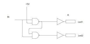
You mean something like this?

Input soldered directly to DEEM.
Output soldered to a R + Led
You mean something like this?
Input soldered directly to DEEM.
Output soldered to a R + Led
DEEM to the input of one of the six inverters of a 74HCT04, 2.7 kohm resistor from the inverter output to the cathode of the LED, anode of the LED to the +5 V, other five inverter inputs to ground. The T in 74HCT stands for TTL compatible, meaning that anything from 2 V to 5.5 V is recognized as a high level. You can also use two inverters in a row, a resistor and a LED to ground, if that is more convenient.
I did something similar with the error flag from the SAA7210 (EFAB signal, Error Flag from the A-chip to the B-chip, that is from SAA7210 to SAA7220). I inserted a transistor with a LED + resistor in its collector. The LED blinks when there is an uncorrectable error in the frame.
@CondeMor you already have the transistor pos. 6534...
@CondeMor you already have the transistor pos. 6534...
Thanks everybody for the replies!!
@Icsaszar I think I’ll choose your idea: replace the resistor 3655 with a led+resistor
But the original resistor 3655 is 100K… do you think that a 10k resistor in series with a standard led will make the same value than the original 100k resistor?
@Icsaszar I think I’ll choose your idea: replace the resistor 3655 with a led+resistor
But the original resistor 3655 is 100K… do you think that a 10k resistor in series with a standard led will make the same value than the original 100k resistor?

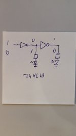
Why 2 led? I only need one to see if de-emphasis is enabled 🤔Jeśli prąd wynosi tylko 0,2 mA, najlepiej użyć bufora. To tylko jeden układ scalony, dwa rezystory i dwie diody LED.
LOL you are right!!🤦♂️ON and OFF
But I think I'll use only the second led (ON) with yellow or orange color just to inform the listener that de-emphasis is enabled.
Must the input of the first gate be connected directly to DEEM as I drawn in the first picture?(emitter of the transistor 6534, it's the same).
Or must it be connected to the collector of 6534?
Last edited:
To DEEM, and use TTL compatible CMOS inverters (74HCT04).
When you connect the collector of 6534 to a CMOS inverter, its ESD protection will clamp the low voltage to about -0.7 V, while it is supposed to be -15 V to properly switch off the JFETs. All CDs are then played with de-emphasis, also those without pre-emphasis.
When you connect the collector of 6534 to a CMOS inverter, its ESD protection will clamp the low voltage to about -0.7 V, while it is supposed to be -15 V to properly switch off the JFETs. All CDs are then played with de-emphasis, also those without pre-emphasis.
Finally I used a transistor + led + resistor. I did the mod to a Philips CD460 that I bought recently with some faults.
Base of the transistor to a 10k resistor, goes to DEEM signal.
Emitter of the transistor goes to GND.
Collector to 250 ohm resistor + led, goes to +5v.
Now, when DEEM goes HIGH, its 3,5v. Then the transistor goes to saturation and the led turns on.
The CD460 was completely broken:
- CD tray closes but wont open. The problem was one faulty transistor that controls if the motor runs in one direction or the other. Changed the transistor, problem solved.
- Display dead. Its the famous NSM4202.
When manipulating the display board while the cd460 was turned on, the display showed numbers for a few seconds but with 2 segments missing. I think that the problem is the NSM4202 itself, not the other components. Now I have to make a new one display module following the post fron Bram Jacobse. I’ve never done something like that so… what’s the chespest way? There’s somebody who sells the printed PCB? Or may I have to send the gerbers to a random aliexpress pcb seller?
I’m writting Bram via email and MP but I have been waiting for many days without a reply 🙁
Personally, I would use either the setup with NAND gates/inverters or a discrete, logic-compatible MOSFET tied to the DEEM line. Hook the gate to DEEM, source to ground, and drain to LED + series resistor to VCC.
CD4011 would be a good choice for a NAND gate. 74HCT00 would likely work also.
2N7000 is an example of a MOSFET that would work. It comes in a DIY-friendly TO-92 package. The 2N7002 has lower threshold voltage, but is only available in SMD.
The advantage of using a MOSFET is that the gate does not load down the DEEM signal.
Tom
- Home
- Source & Line
- Digital Source
- [Mod] De-emphasis LED indicator