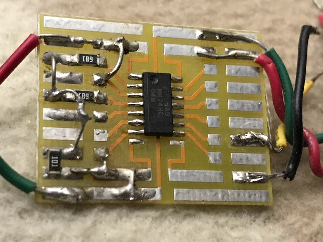
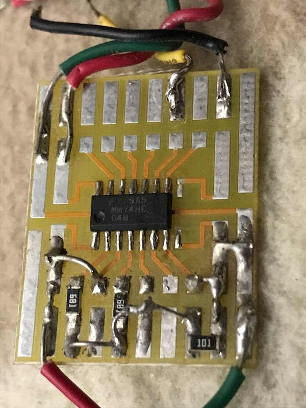
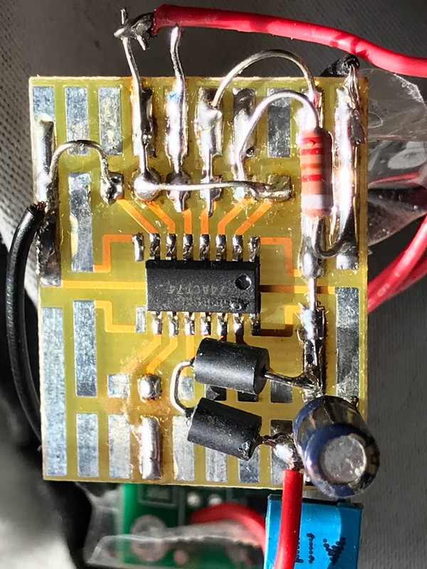
I built this many years ago, on a small proto board (both photos, same device from different angles). All smd components, based on the MM74HC quad 2-input NAND gate.
Some kind of digital audio tweak (reclocker, etc???).
Anyone have a guess on what it may be?
Some kind of digital audio tweak (reclocker, etc???).
Anyone have a guess on what it may be?
Most inverter CMOS gates may be converted into low gain linear amplifier biasing them with a high value resistor from input to output (10M typical). While the signal is sufficiently low to prevent output clipping. CD4069 and 74HC04 are into those groups. There was some theory about the use of them in al old National Semiconductor handbook. Never tested its distortion but 10x gains are simple and useful.
NAND and NOR gates too, and can be used as gated or enabled/disabled amplifiers. Once I did it with an 4011 NAND. Avoid Schimtt devices (CD40106 or 74HC14).
NAND and NOR gates too, and can be used as gated or enabled/disabled amplifiers. Once I did it with an 4011 NAND. Avoid Schimtt devices (CD40106 or 74HC14).
I'm guessing whatever it was didn't work because the chip you have fitted looks like a 74HC04 Hex invertor and not a NAND gate 😉
Fwiw it looks like a buffer/invertor and level shifter as configured.
Fwiw it looks like a buffer/invertor and level shifter as configured.
Two inverters with their inputs tied together, their outputs tied to 680 ohm resistors, the other sides of which are tied together and connected to a 100 ohm resistor to ground, with four other inverters with open inputs and outputs, two loose wires and no supply decoupling.
If there were an output coupling capacitor, I'd say a converter from CMOS to S/PDIF levels.
If there were an output coupling capacitor, I'd say a converter from CMOS to S/PDIF levels.
Yes, output coupling capacitor is missing, but my guess is TTL to S/PDIF.
https://sound-au.com/p85-f6.gif
https://sound-au.com/p85-f6.gif
Yes, but 74HC04 is TTL compatible. TTL to S/PDIF is used for optical to S/PDIF conversion. But nowadays CMOS level optical receivers exist also.
It has a typical switching threshold of 50 % of the supply, 70 % maximum, so it is not TTL compatible when working off a 5 V supply. You might call it sort of TTL compatible when the supply is 3.3 V, except that its ESD diodes can then be blown up by anything over 3.8 V or so.
Strictly speaking you are correct. However 74HC04 at 5V would work fine with 5V optical receiver (e.g. TORX179). But it would not necessarily work correctly at 3.3V with TORX147 3.3V optical receiver which has minimum high voltage output as 2.1V.
Just remembered this from many many moons ago. This used a 74HC04
https://www.diyaudio.com/community/...diy-transmitter-and-super-clean-drive.196263/
https://www.diyaudio.com/community/...diy-transmitter-and-super-clean-drive.196263/
Yes, that photo in the OP was most likely related to SPDIF. And it probably worked, otherwise I would have deconstructed it.
A related project, absolutely SPDIF, and still a highly useful overperformer (device on RIGHT in bottom photos; ignore the other devices in the photos -- they are meant to confuse).
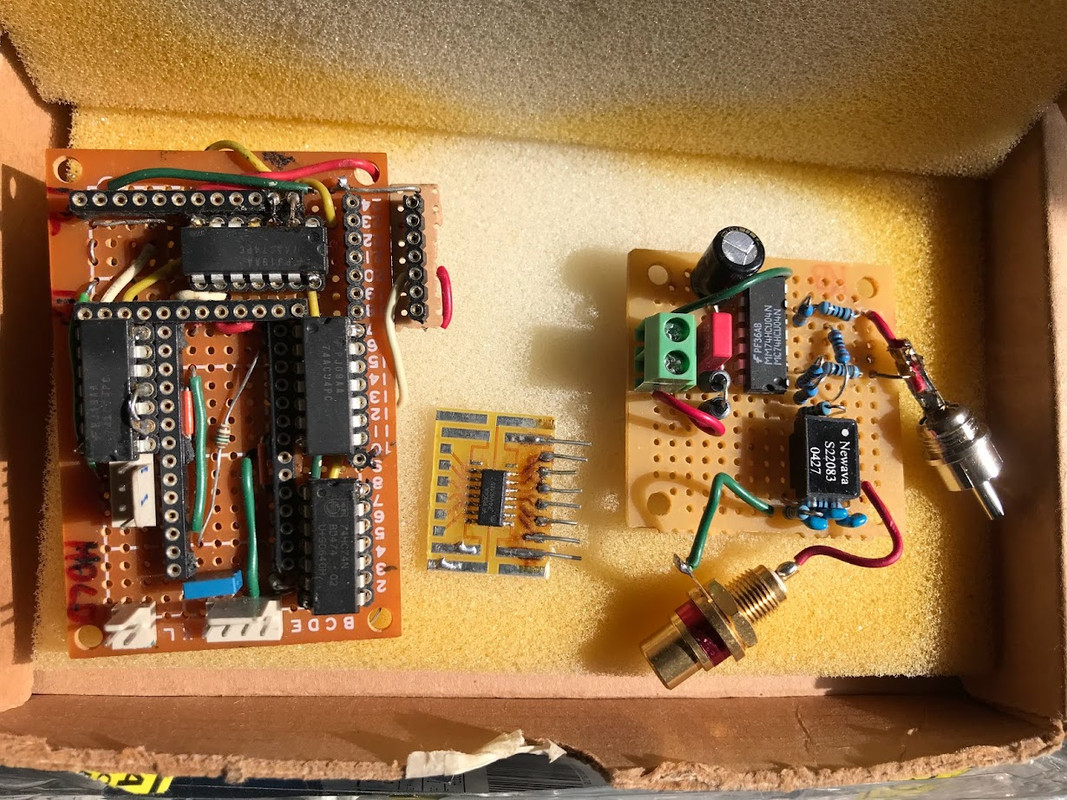
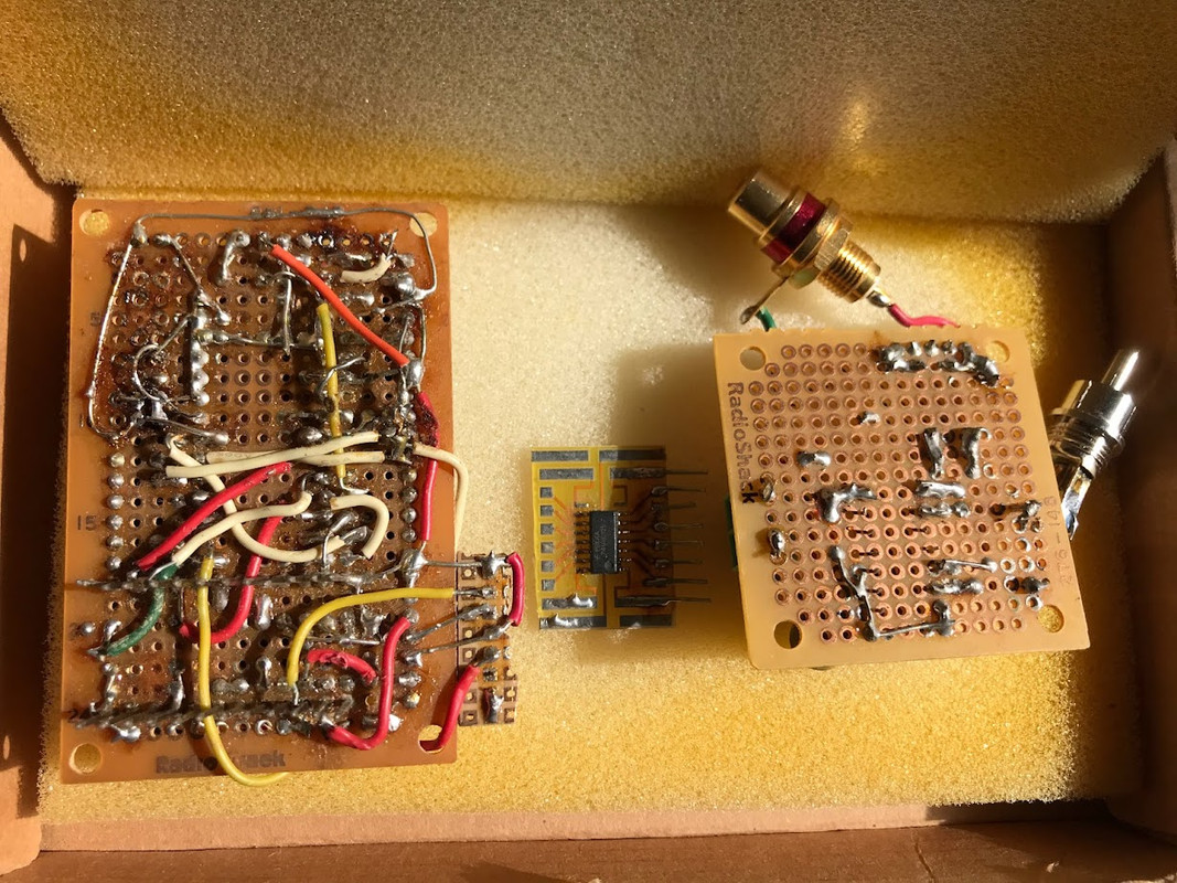
BTW, try to guess the function of this device in the photo below:
A related project, absolutely SPDIF, and still a highly useful overperformer (device on RIGHT in bottom photos; ignore the other devices in the photos -- they are meant to confuse).
BTW, try to guess the function of this device in the photo below:
- Home
- Source & Line
- Digital Line Level
- MM74HC mystery project -- what is it?