Dear all,
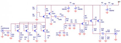
I've built this phono preamp [sch attached] ... but why thats unstable ... if i turn on ... the left side is okay ... but the right one is ready 1 minute later ...
Can you help me? ... Any comment was appreciate ...
Regards:
ragil.hastomo
I've built this phono preamp [sch attached] ... but why thats unstable ... if i turn on ... the left side is okay ... but the right one is ready 1 minute later ...
Can you help me? ... Any comment was appreciate ...
Regards:
ragil.hastomo
Attachments
First of all: Decoupling caps! Try to put 10-100 nF, ceramic or polyester (small 63 V are good!) in parallel with your big mamas. You may also have too high ground impedance, small and thin copper traces.
I think also that your parallel connection of the output stage is unwise. Try to insert source resistors so you have a controlled current sharing. Make the value 1/10 or 1/5 of the total value. The result is attenuation of 0.9 or 0.8.
I suggest also that you increase the current of the output buffer to as much as the fet's can stand. Otherwise you will get a rather high output impedance (loss of high frequencies).
R1 is a little bit high I think. I would have chosen 100-390 ohms. In fact it's better to have lower R and bigger C's. If you have a "stable" power supply voltage you will probely have better chances of getting stability.
Have you considered the output impedance of the first stage which feeds the RIAA network? I think you will get an error here due to unsufficient drive capability.
Hope this can be to any help.
The input stage
The input stage has very little gain if I'm not mistaken, approx. < 5. The sources of the input JFET's must be decoupled if you want higher gain. The caps must be big, > 1000 µF at each fet. Haven't done any calculating so the value is rough.
The DC gain (or at 50 Hz) must be 300 to 1000 depending on pickup.
As Jocko Homo notice, the RIAA network don't look right...but I haven't done a calculations here either.
I suspect that you want to design this RIAA amp by yourself but if you want to take a shortcut, take a peek at Nelson Pass' (or Mr Wayne Colburn's) Pearl phono amp. The basic idea is the same.
http://www.passdiy.com/projects/pearlono1.htm
dhengkoel said:Dear all:
Thanks for your comments ........
I revised my schematic ... and I will try it tomorrow ... I post the report as soon as possible ...
Regards: ragil.hastomo
dhengkoel,
in your last schematic, you would overload Q2, because it must take several times nearly the full Idss of the input JFETs.
BTW, the 2SK30 is not happy when paralleling in phono input stages. I tried it. One is enough - if not take a 2SK170, as Werner already said.
BTW (2), the 2SK30 has low internal capacitances, and a very high output impedance. You do more harm with cascoding that input stage, than getting benefits, if at all.
So, please, make your circuit simpler. A single 2SK30 in the input, without cascode, that is enough.
regards,
Hartmut
Also skip the gate resistors, adds noise. Use them ONLY if you are having trouble unstability.
Wrong, wrong ,wrong,, wrong..........
Just add them and you won't have to worry about it. Or the noise.
Jocko
- Status
- This old topic is closed. If you want to reopen this topic, contact a moderator using the "Report Post" button.
- Home
- Source & Line
- Analogue Source
- :: mm pre phono ::


