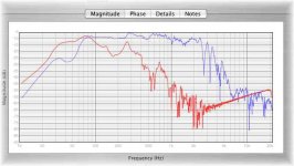
So after thinking for quite a while that I had serious room issues around 80Hz I took my microphone off of it's stand and put it on a book for some nearfield port measurements. I'm such a noob . Apperantly the MLTL is not performing quite like the simulations said it would, although it is quite impressively close. Every thing is the same as the simulation is except for a large hump at 80Hz. Ussually under these circumstances I would just lengthen the ports, but the driver has the expected dip in the 40Hz range, so the port is tuned where it should be. The only thing different from the MLTL sim is the small 2L sealed enclosure inside the larger MLTL. I'll try lengthing the ports, but I don't feel like this will really solve my problems. Any insights?
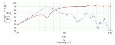
I'll attach the measurements and the sim from Martin's worksheet.
Thanks
Joe
Oh the cabinet demensions are 45"x14.5"x10" (off the top of my head, I may be off by a tiny bit...)
. Apperantly the MLTL is not performing quite like the simulations said it would, although it is quite impressively close. Every thing is the same as the simulation is except for a large hump at 80Hz. Ussually under these circumstances I would just lengthen the ports, but the driver has the expected dip in the 40Hz range, so the port is tuned where it should be. The only thing different from the MLTL sim is the small 2L sealed enclosure inside the larger MLTL. I'll try lengthing the ports, but I don't feel like this will really solve my problems. Any insights? I'll attach the measurements and the sim from Martin's worksheet.
Thanks
Joe
Oh the cabinet demensions are 45"x14.5"x10" (off the top of my head, I may be off by a tiny bit...)
Attachments
Which work plans are you using? Also, did you measure the drivers to ensure that the parameters are right? The two graphs are really quite close for the extend of modeling provided. Since it does not model the exact shape, you can't expect the results to be exact. I would first consider smoothing the horn so that transition is smooth. Currently it looks like the horn in the box is a combination of flat surfaces.
When doing near field measurements, I have had the best results when the speaker is elevated and placed horizontal on a table or workbench. This removes any reflective boundary conditions from the measurement.
If your speaker was standing on the floor, and you placed the mic down near the port opening, then your measurements are being influenced by the floor reflection. The worksheets on my site do not include the floor in the model. I have newer worksheets that I am still developing that include the baffle step and the floor and they produce slightly different results. This may be the cause of your difference between modeled and measured results.
Hope that help,
MJK said:When doing near field measurements, I have had the best results when the speaker is elevated and placed horizontal on a table or workbench. This removes any reflective boundary conditions from the measurement.
If your speaker was standing on the floor, and you placed the mic down near the port opening, then your measurements are being influenced by the floor reflection. The worksheets on my site do not include the floor in the model. I have newer worksheets that I am still developing that include the baffle step and the floor and they produce slightly different results. This may be the cause of your difference between modeled and measured results.
Hope that help,
That could be it. Don't know why I didn't think of that. I'm still learning all the in's and out's of speaker measurement. I'll try placing them on a table and see what I come up with, thanks. BTW I was quite impressed at how close the port response was to the simulation, very cool.
Joe
I thought of one other possibility that might explain the depression in the port response. I have noticed that with some higher Qts drivers that the BL product is not very high and near the box tuning frequency the driver seems to run out of "push" to keep the port output building to a peak. This will lead to a dip in the port response similar to what your measurements show. Did you measure the T/S parameters of the driver and if so how did you determine BL? If you go into the simulation and start reducing BL, being careful to update the remaining T/S parameters so they are consistent, you might notice that a shape similar to your measurements starts to appear in the port response.
Well when I first built these I didn't have any measurement equipment so they were simulated with just the factory specs. Not the best option I know. I now have the means to calculate T/S parameters. If I measure them and the BL is lower than what I had calculated for what is the best way to fix this apart from building new cabs? I'll test them tonight and let you know, I would think this might be the case since even with time gating everything below 60Hz the bump at 80Hz is still there. I would think that gating it that heavy with a nearfield measurement would remove any real room modes or standing waves. Of course I still have a lot to learn and I could be wrong.
Joe
Joe
Well I flipped my cabinets over so a to avoid any floor loading, and the plots look the same. I probably won't have any time to test the T/S parameters until maybe this weekend, but given what you said I would have to imagine that the low BL would have to be the cause. Unfortunatly I'm running on a Mac and am unable to run your worksheets, otherwise I could sim away till my hearts content and find the best solution. GM was kind enough to share some sims he had done for this driver, which is where I got the original cabinet design. Do you think the problem is a cause of too large of a cross section in the cabinet? Is there any kind of fix outside of rebuilding my cabinets?
thanks
Joe
thanks
Joe
Joe,
Looking at your measurement plot, my only guess is that the T/S parameters might be off. I looked back in my notes and found some plots that looked like this for high Qts and low BL drivers. Measuring the drivers will either confirm this or cause us to look elsewhere for the differences.
I guess the question is, how do the speaker sound? If they sound good then I don't think you need to make any changes. It is always very rewarding when the measurements and the predictions match, it tells you that your modeling was accurate and you understand what is going on in the enclosure. But the bottom line is still how the results sound and are you happy with them.
Yeah i cann't say I completly satisfied with the bottom end. I had thought my bass issues were due to room modes. Now that I know that it's cause by the cabinet I definatly want to fix it. I'll measure the drivers this weekend. I figure if the cross-sectional area of the cabinet needs to be shrunk I can do that with rectangular pieces of wood and liquid nails, or if the ports need to be lenghtened I can do that as well. My brother has a PC for work and maybe I can get him to do some modeling for me.... see how things look with measured T/S parameters.
Joe
Joe
- Status
- Not open for further replies.
- Home
- Loudspeakers
- Full Range
- MLTL port tuning