So we are given task to make a mixer circuit with:
Three (3) high impedance microphone-level inputs (unbalanced), two (2) high impedance line-level inputs
Microphone input section
- Input impedance (Zin): 800 ohms
- Level gain (Av dB): 42 dBu
Line input section
- Input impedance (Zin): 20 kohms
- Level gain (Av dB): 25 dBu
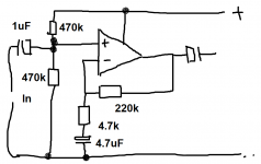
So i have this image found in a book
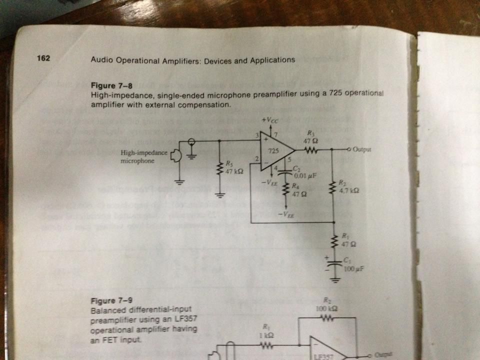 . I read also in this book that the R5>= 10Zmic. Does this mean that the Zin = 800ohms is also the Zmic which is the output impedance of the mic? I also have no idea how to do the line input part. Im confused can anyone enlighten me. Sorry im only a beginner in design.
Three (3) high impedance microphone-level inputs (unbalanced), two (2) high impedance line-level inputs
Microphone input section
- Input impedance (Zin): 800 ohms
- Level gain (Av dB): 42 dBu
Line input section
- Input impedance (Zin): 20 kohms
- Level gain (Av dB): 25 dBu
So i have this image found in a book
That is a really old book. Peavey is using NJM4560 dual in line package op amps for their mixers. I redid a Herald electronics mixer that originally had NJM4558D's with ST33078's. 725's were two decades ago or more. The 5532 IC was available then, and still is used a lot today for low noise and low price.
Microphones come in two classes, dynamic and condenser. Dynamic mikes tend to be about 10kohm impedance. Phantom Powered (48 vdc) condensor mikes have an output impedance in the tens of ohms. This allows them to drive long cables <33 m without losing the high frequencies. Better music uses condensor mikes, DJ's use dynamic mikes like the Shure SM58 or even the SM48.
Line level inputs tend to be for devices putting out 1.6 VAC full scale, or 2 VAC in the case of some more modern devices. Power amplifiers tend to have the same specification as the input level for full power, although many PA amps have an input attenuator. This means the line level stage must have gain from about 5 to 1:1.
There are many mixer schematics on this forum that are better than these old ones. Check this thread.http://www.diyaudio.com/forums/analog-line-level/167604-basic-mixer-design-need-input.html Ron Elliot's westhost site is one of the standards of the internet of internet schematic projects, I believe one of the schematics is shown in pdf (adobe) form on the above thread.
Anyway, gain of an op amp is basically Rf/Rin where the Rf is the feedback resistor from the output to the minus input of the op amp. I modified a commercial mixer kit with hissy hummy sound to sound very decent, in this thread: http://www.diyaudio.com/forums/anal...improving-disco-mixer-mid-fi-performance.html There is an idea there for a power supply for 5 to 6 op amps using a surplus wall transformer, two 5W zener diodes, some resistors and caps. A headphone amp included in the mixer would require an actual voltage regulator circuit or bypass power transistor on the zener diode.
Last edited:
Mixer circuit pre-amp
For Mixer part, we are required to have: Three (3) high impedance microphone-level inputs (unbalanced), two (2) high impedance line-level inputs.
For microphone section:
-Input impedance (Zin): 800 ohms
-Level gain (Av dB): 42 dBu
For Line input section:
- Input impedance (Zin): 20 k
- Level gain (Av dB): 25 dBu
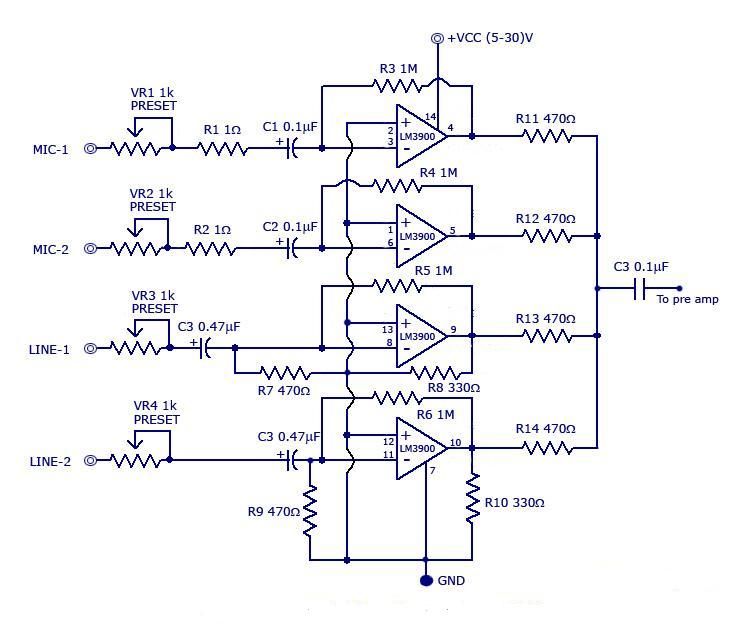
i have here a sample mixer circuit i saw on the internet. my problem is, how do i accomplish the requirements above. i have no ideaaaa 😕
For Mixer part, we are required to have: Three (3) high impedance microphone-level inputs (unbalanced), two (2) high impedance line-level inputs.
For microphone section:
-Input impedance (Zin): 800 ohms
-Level gain (Av dB): 42 dBu
For Line input section:
- Input impedance (Zin): 20 k
- Level gain (Av dB): 25 dBu
i have here a sample mixer circuit i saw on the internet. my problem is, how do i accomplish the requirements above. i have no ideaaaa 😕

James, I have merged your threads together. Starting more than one thread on the same topic spread across forums is confusing.
As to your problem...
You need to design an opamp input stage for each of the inputs needed. That allows you to accurately match each input to your specification.
To mix them you need a "virtual earth" configuration using an opamp (similar in concept but not quite the same as in the post above). Look up opamp based mixers.
The LM3900 (obsolete now) isn't typical of opamps as we know them today and operates slightly differently. Its called a "Norton" type amplifier and can't be directly swapped into the majority of opamp circuits without some redesign. I would stick to something like the TL071/2 or 4 type devices (singles, duals and quads) as these are easy to work with.
thank you sir, my problem is how to match the input impedance of the mic to the input stage of my opamp. can seem to find any on the internet. im thinking of using a bjt instead of op amp since i can compute for the input impedance of a bjt using h-parameters.
The input impedance of an opamp circuit is defined by the input resistor (which you select). For noninverting configurations its the resistor that goes from the +input to ground and for inverting configuration it is the resistor in series with the input connecting to the - input.
For your applications yes. In that first circuit you posted, R5 (47K) is the input impedance the circuit presents to the outside world (both at AC and DC as there is no input coupling cap) You could make it 1meg or 1 ohm and that would be the input impedance.
If you use LTspice you can simulate the circuit and "prove" the impedance is as described.
If you use LTspice you can simulate the circuit and "prove" the impedance is as described.
hi sir! i just wanna ask how about on the other circuit? and how do i check the impedance on LTSpice?
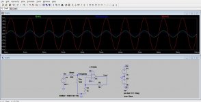
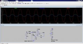
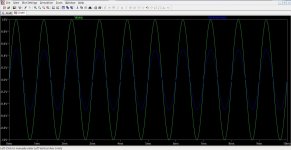
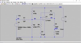
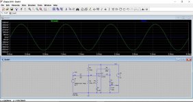
Here is how you can check the input impedance on any amp either for real or in simulation.
Can you see how it works ? and what Rtest does ? Look at the relationship of the voltages. Can you see how it "proves" the input impedance is the same as Rin ? The last picture shows the scale better of "Vin" and "Vinopamp"
Can you see how it works ? and what Rtest does ? Look at the relationship of the voltages. Can you see how it "proves" the input impedance is the same as Rin ? The last picture shows the scale better of "Vin" and "Vinopamp"
Attachments
Hello!
Recently I found 2 vintage soviet microphones октава мд-47 and мд-201. I thought they would do great for vintage type voice recording. When I was testing them I noticed that their output is extremely low. I added a preamp from an old DVD player but that didn't help much. Could some modifications to the circuit help rising the signal?

Thanks in advance!
Recently I found 2 vintage soviet microphones октава мд-47 and мд-201. I thought they would do great for vintage type voice recording. When I was testing them I noticed that their output is extremely low. I added a preamp from an old DVD player but that didn't help much. Could some modifications to the circuit help rising the signal?
Thanks in advance!
The problem is that the opamp is configured in inverting mode and that means the input impedance is extremely low at 4.7k (set by R4). That low impedance is killing the voltage the mic produces.
You could reconfigure it if you are careful. I don't think you need the cap across the 220k, or at least nowhere near that big, and also definitely not the 1nF at the output.
You could reconfigure it if you are careful. I don't think you need the cap across the 220k, or at least nowhere near that big, and also definitely not the 1nF at the output.
Attachments
Hi there!
Thank you for your fast reply. Your design is great but the only question is will it work with 12V single supply? sorry that I didn't mention that earlier.
Thank you for your fast reply. Your design is great but the only question is will it work with 12V single supply? sorry that I didn't mention that earlier.
Yes, 12 volts is enough for that opamp and the 470k's bias the opamp to approximately half supply voltage. The gain is equal to the ratio of the feedback resistors plus 1 and so is (220,000/4700)+1 which is 48. If that is a bit high then reduce the 220k to suit.
Yes, its correct. A quick check of the voltages on the opamp pins should go a long way to confirming its OK.
The + input (non inverting input) should be at approx. half supply voltage as dictated by the two 470k resistors. The output should also be at this same voltage, as will the inverting input.
The + input (non inverting input) should be at approx. half supply voltage as dictated by the two 470k resistors. The output should also be at this same voltage, as will the inverting input.
Yes, there was the problem, the 470k resistor wasn't grounded. Thank you very much. Works great.

- Status
- Not open for further replies.
- Home
- Source & Line
- Analog Line Level
- Mixer Pre-amp