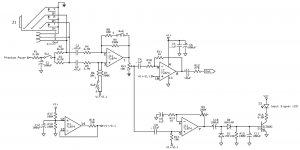
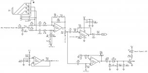
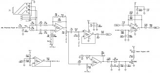
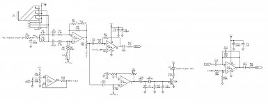
I am designing a mixer with the input channel below. I would like to see what your thoughts are.
It runs on a 15V single supply.
The IC1A is a simple differential to single ended converter circuit that suits my purpose. As long as the XLR Mic input works with a single supply. I've seen it working with a dual supply.
IC1B is a input signal indicator circuit.
IC1C is basically to make sure other channels don't interfere with the input signal indicator circuit. I'm not sure if this needs to be a non inverting amp or inverting amp. And can be used for gain if needed.
IC1D is the virtual ground circuit.

Microphones want 48V applied through 6k81 resistors, instead of 8k2. And ground mark of the fader pot looks kind of strange.
Right, I did remember the 48v but it's not written in.
The ground is because I have both signal ground and power grounds. That just happens to be the only signal ground, unless you think the input indicator should be signal grounds as well.
Thank you for your thoughts.
The ground is because I have both signal ground and power grounds. That just happens to be the only signal ground, unless you think the input indicator should be signal grounds as well.
Thank you for your thoughts.
I mean your virtual ground, is it half way from the real ground, or connected to it? If half way, on fader you have half of DC.
IC1a is biased to V/2, so the pot on its output should return to V/2, not to ground.
C4 R10 set a bass roll-off at 1.6KHz, or 450Hz if RV1 is set half-way. While you could set C4 larger, I don't think R10 R11 need to be anywhere near as low as 1K; that's heavy work for TL074. Go 10K at least, which suggests C4=10uFd. If 10uFd is awkward, run IC1c as non-inverting, then you can bias with 1Meg and strap pin 8 to 10 to get your unity gain.
C2 C3 against 3.9K seem to give a 90Hz bass-cut. That's not the right answer; this type diff-amp input impedance is not a simple function of the resistors (and varies with input balance).
The jump in IC1a gain from 2.5 to 100 seems a bit large, unless you have two distinct types of input sources mike and line.
> IC1C is basically to make sure other channels don't interfere with...
And to buffer your 10K pot against heavy loads.
OTOH, if you really want R12 27K at the output, there's no reason to buffer the pot.
And arguably "Signal present" could be before the pot(?) in which case the opamp pot and 27K will swamp any back-leak from other sources.
Ok, so I biased RV1 to V/2 instead of ground.IC1a is biased to V/2, so the pot on its output should return to V/2, not to ground.
I changed R10 and R11 to 10K, leaving C4 as .1uF. This should give about 150Hz roll off.
These values were right off another piece of equipment and it works. The only difference is I'm using a single supply and they had a dual supply.C2 C3 against 3.9K seem to give a 90Hz bass-cut. That's not the right answer; this type diff-amp input impedance is not a simple function of the resistors (and varies with input balance).
I wanted the signal indicator after the pot so that the indicator LED will come on only when RV1 is turn up to a certain level.
Yes, this is for Mic/LineThe jump in IC1a gain from 2.5 to 100 seems a bit large, unless you have two distinct types of input sources mike and line.
The R12 27K resistor is the mixing resistor for the other channels. If 27K is not right, what should I have it at?
I appreciate all input.
Thank you

Ok, so when I biased the Pot to V/2, the pot had no control over audio and the audio is on all the time. With the pot grounded, it works. Also, my phantom voltage starts at 47volts on the input. After R1 it drops to 28.5 volts. And there is no voltage after R2, and R3.
I found my problems. I had forgot to put R19 into the PCB. Afterwards the V/2 on the pot was fine. I had also grounded the switches on the input jack. Doing so grounded out the xlr when it was inserted. I have also changed R2, and R3 to 6.8K. Finally I have changed IC1C to a non inverting buffer.
If I wanted to increase the gain on IC1C, does it require a capacitor connected between the resistor and ground like C9?
I have not yet gotten the inverting summing amp. All opinions and observations are welcome.

If I wanted to increase the gain on IC1C, does it require a capacitor connected between the resistor and ground like C9?
I have not yet gotten the inverting summing amp. All opinions and observations are welcome.

- Status
- Not open for further replies.
- Home
- Source & Line
- Analog Line Level
- Mixer Channel for observation
