Hello all,
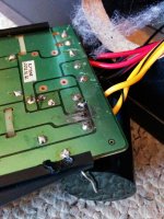
In the process of removing crappy old capacitors (which had bent arms and were glued down to the board [emoji35]) I couldn't help but displace one or two of the solder pads despite my best efforts at taking my time and being careful.
I know that running wire from the preceding and subsequent pins to the arms of the capacitor in question is one last resort, but schematics for this model are non-existent and I'm not 100% which parts to connect it up to.
In the first crossover, I think it should be connected to the +/- HF wires in yellow:

Any thoughts?
Thanks
In the process of removing crappy old capacitors (which had bent arms and were glued down to the board [emoji35]) I couldn't help but displace one or two of the solder pads despite my best efforts at taking my time and being careful.
I know that running wire from the preceding and subsequent pins to the arms of the capacitor in question is one last resort, but schematics for this model are non-existent and I'm not 100% which parts to connect it up to.
In the first crossover, I think it should be connected to the +/- HF wires in yellow:

Any thoughts?
Thanks
- Status
- Not open for further replies.