
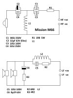
So, I'm going to replace all the remaining Poly Caps on the HF circuit. If you look at the circuit diagram I provided earlier (and below), there are two pairs of caps in parallel. For the C2 & C4 pair, I am simply going to remove the old C4, the 335J (3u3F), and leave only my new 33uF Poly in place. This should barely make any difference to the sound, as my replacement Poly for C2 is 33uF, which is well within tolerance of the original 32+3.3 combo of 35.3uF. That should be ok?
For the other pair, C1 & C3, 805J & 105J (8uF & 1uF = 9uF), I have a choice of replacing them both with either a single 8u2F Poly - slightly less than the 9uF combo - or a single 10uF, slightly more! Which one should I fit?!
Do I take it that a larger cap in series with the signal allows 'more' lower frequency through? So, if I choose the 10uF over the 8.2uF, the tweeter will receive down to a slightly lower frequency?
In any case, I'm guessing that the difference will be marginal?
Thanks for any pointers.
Attachments
To summarise:
The original values were 35.3 uF and 9 uF.
Your proposed values are 33 uF and 8.2 (or 10) uf .
Since this is a 3rd order high pass filter, I think that simultaneously raising the value of both capacitors would produce a lower crossover frequency.
I'd go for 33 uF and 8.2 uF, but mainly because I think the difference between those and the original values is unlikely to be audible.
The original values were 35.3 uF and 9 uF.
Your proposed values are 33 uF and 8.2 (or 10) uf .
Do I take it that a larger cap in series with the signal allows 'more' lower frequency through?
Since this is a 3rd order high pass filter, I think that simultaneously raising the value of both capacitors would produce a lower crossover frequency.
I'd go for 33 uF and 8.2 uF, but mainly because I think the difference between those and the original values is unlikely to be audible.
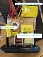
Pleased to report it's 'sorted'! At least, the cause has almost certainly been eradicated, and my suspicion must fall on C1, as that's the larger of that pairing, and the tweeter attenuation effect was significant. But, I don't know for sure - I cannot test them - but I also don't care!
What I did was to remove C4, leaving just my already-replaced C2 - a 33uF (so, overall, that's down from the original 35u3F combo). I then removed both C1 and C3 - combined 9uF - and had a choice of 8u2F or 10uF to replace them by. I went for the latter, Galu, for the simple reason that I'd reduced the other pair's value from 35u3F to 33uF, so thought I should perhaps 'up' this one a wee tweak? Scientific, yeah? Cough.
If you think I've done wrong, please say 🙂
Anyhoo, I wired up both tweeters in their cabinets using only their HF inputs, and repeated my previous 'HF' test - an FM station off-tune. The result was that both immediately outputted at near-identical levels - so a 'cure'! - with the 'fixed' side, if anything, a touch crisper, higher-freq. (I say that last bit not in the sense that it's 'better' - I don't know if it is - but just as an observation).
Added in the LF side, and blasted out Red Rain by t'Gabriel - he was inside my heed, man.
So, it's 'fixed', in that the culprit has been found, removed, and replaced. And it wasn't an Electrolytic, lawdie!
Of course, I have no idea how the speaker compares with Mission's original intention, but - man - I like it!
Do I try swapping the 10uF with my 8u2F just to test? I don't think I'll bother - unless there's good reason to. To be honest, unless I can compare two sound outputs literally side-by-side, switching instantly between them, I think such comparisons are largely moot. But, will I replace the other side's crossover's caps to match? Probably 🙂
Thanks all.
Attachments
- Home
- Loudspeakers
- Multi-Way
- Mission M66i Crossover faulty