Can't remember so I will ask, do we need an insulator between these and the chassis?
You need 2. They mount to the chassis with a bolt. Connect the transformer secondaries to the 2 tabs marked "~" (meaning AC) and connect the input of the PSU board to the "+" and "-" . It's easy!
If you are using the Paul Daniels power supply boards with the diode boards with the MUR 3060 devices he recommends, then yes, you must use insulators. The square block bridges rarely do.
Whoops, I see 6L6 covered that in #12. I piped up because I installed them in my dual mono F-5, all 16 of them with grease, before I saw they didnt work like the block bridges do...I had to remove, clean, install sil pads and re assemble all 16 of them!
Russellc
Last edited:
If you want to make a case similar to an Aleph, use the Peter Daniel boards. With the FETs on the sides you can make them mate to 90deg angles. The Cviller boards look very nice as well, don't let me talk you out of those... I think I will use them on my next build, just to try them...
If you make Monoblocks with a single heatsink, either will work very well.
If you make Monoblocks with a single heatsink, either will work very well.
So what about the JFETS? how do i determine the orientation on Q1, Q2, Q5, and Q6, in their mounting holes on the Circuit boards? i dont know what ohm loads are supposed to go which direction?
Which boards do you have?
The Peter Daniel boards have all the small Qs clearly marked - the input jfets (Q1,2) and the current dumpers (Q5,6) all have a flat side and a rounded side to the black plastic package. There is a corresponding diagram on the board - look at the following photo:
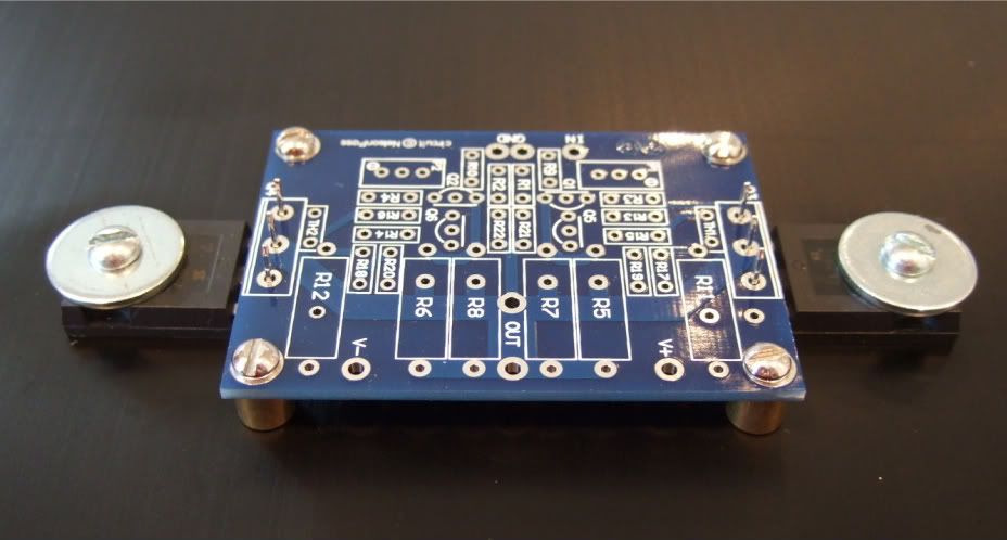
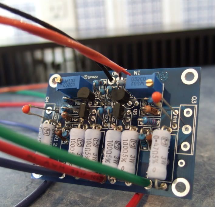
And here you can see the transistors installed is the same direction indicated on the PCB stuffing guide.
The Cviller boards are similar for Q1,2 but the package for Q 5,6 doesn't seem to be as well marked. However, I don't have the board in front of me, and am just looking at photos... That said, the cviller boards do have the pins marked, so grab the datasheet and see which way it needs to go!!
Also remember to be very sure that you have the N-channels and P-channels transistors in the right spots! If you don't, well, you will need to buy more transistors. 🙂
The Peter Daniel boards have all the small Qs clearly marked - the input jfets (Q1,2) and the current dumpers (Q5,6) all have a flat side and a rounded side to the black plastic package. There is a corresponding diagram on the board - look at the following photo:
And here you can see the transistors installed is the same direction indicated on the PCB stuffing guide.
The Cviller boards are similar for Q1,2 but the package for Q 5,6 doesn't seem to be as well marked. However, I don't have the board in front of me, and am just looking at photos... That said, the cviller boards do have the pins marked, so grab the datasheet and see which way it needs to go!!
Also remember to be very sure that you have the N-channels and P-channels transistors in the right spots! If you don't, well, you will need to buy more transistors. 🙂
well unfortunately, i ended up getting a pair of knockoffs, saying they are F5 influenced, but basically are the F5, after figuring out where the traces all go from the pieces, it basically looks like it exactly matches the F5 schematic! it came with the ztx's and the 2SJ, 2SK, and the IRFP outputs. It has markings on the board just like the pictures your showing with the flat sides on one half, but being that it was basically the knock off board, i'm not positive they are correct?
If i recall, CanAm Man has the same boards that i got, maybe i'll get lucky and if he catches his name he can pipe in?
i can get some pictures of my board, unless you can tell me which ohm loads go which direction on the board?
If i recall, CanAm Man has the same boards that i got, maybe i'll get lucky and if he catches his name he can pipe in?
i can get some pictures of my board, unless you can tell me which ohm loads go which direction on the board?
It's not an "ohm load" that you want to measure to determine which way they go, it's the way they are packaged...
ZTX450 - http://www.datasheetcatalog.org/datasheet/zetexsemiconductors/ztx450.pdf
ZTX550 - http://www.datasheetcatalog.org/datasheet/zetexsemiconductors/ztx550.pdf
2SJ108 - http://www.datasheetcatalog.org/datasheet/toshiba/1022.pdf
2SK370 - http://www.datasheetcatalog.org/datasheet/toshiba/1042.pdf
You can determine the lead-outs from these datasheets. Then look at the boards and the schematic to figure out which pin is which and how the device must be placed.
If you want to find more datasheets, just google the "transistor name" and "datasheet", such as "2SX211 datasheet"
Last edited:
Thank you!
So, those beeing 33000uf I would need 4, right?
How many of those rectifiers?
As has already been posted you will need 4 capacitors with Peter Daniels boards or 8 with cvillers pcb's which is what I used with a common power supply for both channels. Boards for both capacitor banks and rectifiers are still available from Christian.
It's not an "ohm load" that you want to measure to determine which way they go, it's the way they are packaged...
ZTX450 - http://www.datasheetcatalog.org/datasheet/zetexsemiconductors/ztx450.pdf
ZTX550 - http://www.datasheetcatalog.org/datasheet/zetexsemiconductors/ztx550.pdf
2SJ108 - http://www.datasheetcatalog.org/datasheet/toshiba/1022.pdf
2SK370 - http://www.datasheetcatalog.org/datasheet/toshiba/1042.pdf
You can determine the lead-outs from these datasheets. Then look at the boards and the schematic to figure out which pin is which and how the device must be placed.
If you want to find more datasheets, just google the "transistor name" and "datasheet", such as "2SX211 datasheet"
I forget what the alternative to the ZTX units is, but I believe they have a different pin out. Look at the data sheet for your part, then see which leg goes where on the schematic.
Russellc
I forget what the alternative to the ZTX units is, but I believe they have a different pin out. Look at the data sheet for your part, then see which leg goes where on the schematic.
Russellc
cvillers V2 boards were marked out for BC550 & BC560's which need to be turned 180 degrees compared to the ZTX units.
cvillers V2 boards were marked out for BC550 & BC560's which need to be turned 180 degrees compared to the ZTX units.
Whoops, I thought the ZTX units needed to be reversed on Cvillers boards! Oh well, either way, safe to look to data sheets and schematic for proper orientation.
On the Daniels boards, the ZTX units go just as the marking on the board indicates, not sure about the BC units on Daniels boards?
russellc
ECO-S1VP153EA Panasonic Electronic Components Aluminum Electrolytic Capacitors - Snap In
ECO-S1VA153DA Panasonic Electronic Components Aluminum Electrolytic Capacitors - Snap In
Can anyone tell me the difference between theese?
ECO-S1VA153DA Panasonic Electronic Components Aluminum Electrolytic Capacitors - Snap In
Can anyone tell me the difference between theese?
EA is 85 deg C, 5.57A ripple current
DA is 105 deg C, 3.9A ripple current
Thank yout, but that only made me more confused. What does that mean. Which one would be more suited to the F5, and why so?
I think that in the context of an F5, there is no significant difference. The 35v rating (which is more than necessary) is a very good thing.
The First Watt amps use 85C rated caps, so again, either will be fine.
Both have the same lead spacing, so fit should be no problem.
In your links, one is priced in USD, the other in DKK, so I'm not sure which is cheaper.
The First Watt amps use 85C rated caps, so again, either will be fine.
Both have the same lead spacing, so fit should be no problem.
In your links, one is priced in USD, the other in DKK, so I'm not sure which is cheaper.
Thank yout, but that only made me more confused. What does that mean. Which one would be more suited to the F5, and why so?
That depends on a couple of things, internal ambient temperature of the case and current draw from the PSU.
Ripple current is the maximum recommended current drawn across the capacitor (or through in coupling applications).
How hot are going to run your heatsinks? If they are nice and cool, go for the EA, but if their on the toasty side, you will need the DA - you can always double up the caps if your running high bias.
The EA will still work with hot sinks (60 deg C), but they won't live as long.
it really has little to do with being suitable for an f5 or not. the EA version has better ripple current rating, so it will take more ripple in the AC line before it will show up at the output, but they are only rated for 85 degrees, while the DA version will not cope with as much ripple, but will cope with higher temperature for longer before drying out. i would go for the 105c personally, but it depends on the case temperatures you are expecting in your particular build what tradeoff is better for you. given the currents in the f5 and given you are using multiple caps i would think the 3.9A ripple rating is fine and it will cope with the higher temp more reliably.
- Status
- Not open for further replies.
- Home
- Amplifiers
- Pass Labs
- Misc. Regarding F5