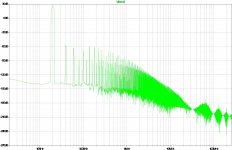
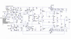
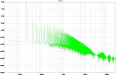
Well, I did not pay enough attention so my circuit drawings were wrong and output crap. The corrected version is attached - both schematics and output harmonics. Floating driver emitters gives best results - 0.00914% at 20kHz. With EF configuration distortions go up at least 10 times with not much difference to quiescent current setting. So basically there is no gain going from version 1 to the last version on these grounds as it uses more components. However, the last version has better bias control and temperature control. I'll test some variations of your versions as well as some of my inventions.
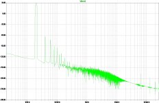
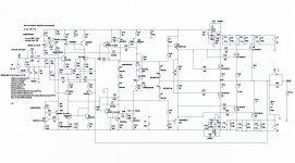
I have also checked simulation of my Stochino version with Exicons. Distortion figures are higher than with verticals but still not bad - 0.0024%. It's harmonics are also attached.
cheers,
I have also checked simulation of my Stochino version with Exicons. Distortion figures are higher than with verticals but still not bad - 0.0024%. It's harmonics are also attached.
cheers,
Attachments
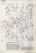
Good, now we've converged and your sims are tallying up with my prototypes. Couple of points about your last sim. I notice that you're using about twice the driver current I used in my prototype, I suspect that this gives lower distortion. I also think my vas current is a little low at 5mA and I will increase it to 10mA by reducing R36 and R57 to 200R. I notice that you've used anti-saturation diodes D3 and D7 instead of transistors to limit the vas current. This is ok with a simple one transistor vas, but Self has shown that if you use anti- saturation diodes with an emitter follower enhanced vas, as here, then the hf performance is degraded. I notice too that you have emitter resistors on the mosfets. These are not usually necessary with lateral mosfets provided that all of gate threshold voltages match reasonably well ( i.e. all of the nfets match and all of the pfets match but not necessarily Vgs(nfet)=Vgs(pfet) ).
Changing R36 and R57 won't improve anything. I tried various values before and 390 is optimal with 2N transistors. Changing these to KSA/KSC and reducing somewhat R36 and R37 gives cosmetic reduction in distortion. Similarly dropping diodes in LTP.
The only tiny drop in distortion gives reduction of source resistors in Mosfets. That results in distortion drop by 0.001% so now distortion with 0.1 ohm source resistors and other "cosmetic" changes thd are about 0.008528% at 20k.
I wouldn't drop source resistors entirely as some do as matching mosfets won't give much unless one has many of these. I use 0.1 ohm source resistors in my ETI477 and I'm pretty happy with that value.
cheers,
PS looking at your last VAS version and Stochino I'd keep that cascode (in Stochino Q9-10 and Q11-12) as these give speed. Q9 works as common emitter with low gain so capacitance collector-base is small and doesn't limit the bandwidth. It's running Q10 working in common base ensuring high gain, wide bandwidth and low input impedance. That much I understand from Stochino's VAS. Diodes (Baker's clamps i think) are to further increase speed. In your last version these would be transistors q17 & 19 and q18 & 20.
Attachments
Last edited:
Thanks for that janusz, I'll keep the cascodes. I saw from an old thread you contributed to that you were then in the process of building a pair of stochino amps - did you ever finish them? Stochino's measurements look very good but I'd be interested to hear your impression of what they sounded like.
I'm rebuilding them now as my PS was humming, mainly due to humming 2x50V 50VA toroid and having 2 toroids on the same ground. So practically it's better to use capacitance multiplier and one toroid or a voltage boost circuits as in Ola amp designed by a friend of mine. VG amp but one has to get some reliable obsolete parts such as BF256C.
Anyway mid and high frequencies are very clean, lows are also good but I think this amp would benefit if 3 pairs of output transistors were used or more powerful pairs such as Toshiba's 2sj201/sk1530 or 16A exicons. As I have two more unused boards I'll try to use 16A exicons as outputs. I need to wire them as with irfp240/9240 as boards are designed for small irfp640/9640s. Only with exicons wires have to go to different pins.
cheers,
Attachments
Last edited: