Hello Everyone,
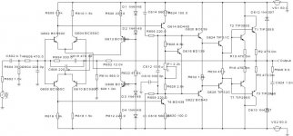
Today, in a moment of extreme boredom, I decided to dissect my Rotel RB971 MKII Power amp, and map out the schematic (which is hopefully attached). What I would like to know is, does anybody know the purpose of C616 / R658 (560p / 220R) - is this for 'miller' compensation? Also, what is the purpose of R654 / C618 / C606(in the differential input stage)? Please ignore the transistor types here - I know they are not the original ROTEL items, but my spice software insists on some kind of parameter (can only be selected from a drop down box, I can't enter a manual value!).
Thanks!
Tony.
P.S. Sorry if this posts twice - the first time I got a warning about the omage being too large - but then no mention of whether I should repost or what???
Attachments
Hi Guillermo,
C610 seems to be a form of frequency compensation for the VAS, not typical lag comp but typical for Rotel, R624 loads the VAS output before the drivers, crude and simple and C612 seems to be another part of compensation, a low pass filter to shunt HF to ground. C616, you are right in it being phase lead compensation.
Best Wishes
Colin
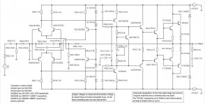
I have posted a clearer rendition of my original schematic, as the export I did obscured some of the circuit.
I have also added some additional comments.
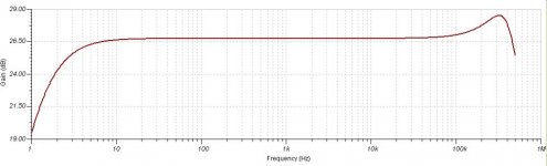
What is interesting to note, is that in a spice emulation (yes, I know spice results are not to be taken to seriously!) - is that with C616/R658 and C614/R656 in circuit, there is a gradual rise in HF response beyond about 30khz, resulting in a huge peak at 328khz. Removing these components results in a flat response...
I'm also aware that the component values used for the spice emulation are not those in th eoriginal Rotel circuit.
It was just interesting to note the response, as the amp has a tendency to sound a little sharp at times, so I wondered if this could be a contributing factor.
I have also added some additional comments.
What is interesting to note, is that in a spice emulation (yes, I know spice results are not to be taken to seriously!) - is that with C616/R658 and C614/R656 in circuit, there is a gradual rise in HF response beyond about 30khz, resulting in a huge peak at 328khz. Removing these components results in a flat response...
I'm also aware that the component values used for the spice emulation are not those in th eoriginal Rotel circuit.
It was just interesting to note the response, as the amp has a tendency to sound a little sharp at times, so I wondered if this could be a contributing factor.
Attachments
this is the classic rotel schematic, the compensation system do not use miller compensation, there are 3 caps for retard compensation for dominant pole.
I forgotten that it's possible make a clone with transistors easy to find in europe, but it's possible make some mods for decrease the very hight NFB.
This compensation approach is mentioned by Self - and he also makes th e point tha t is is sub-optimal.
I would probably have run the front end LTP's at a much higher current (running at about 2-3mA in Rotels design, so each diff amp half is at 1-1.5mA) and added substantial emitter degeneration resistors in 100 Ohm range. Miller capacitors ar e ok if you don't overdo them - 22-50pF. This approach would improve front end and VAS linearity and lower the overall loop gain.
I think the reason they used this compensation approach is to tame an amp with very high loop gain.
Having said that, it should be noted that Rotel amps consistently get good reviews. I guess its a matter of preference on the designers part.
Are you going to clone this amp?
Very similar to the Leach amp, only the front diffamps are implemented differently.
I'm a fan of the Triple Darlington output myself.
I'm a fan of the Triple Darlington output myself.
I have just designed and made a similar amplifier with 100 ohm resistors at transitors's emitters (differential) in the front end and also into VAS bjt, but the output stage has two pair of mosfet lateral channel.
Moreover , I have just designed a preamp/headphone amplifier with similar topology. The NFB is around 46 dB .
Generally my schematics are more complex than these, but several friend of mine have request me this preamp and mosfet amp because they are very cheap and good sounding (there are 16 clones of my preamp...............).
ppa said:the schematic is classic but the compensation system isn't so simple like it is showed.
Hi PP, thanks for the reply. You say that it isn't as simple as it's shown - do you mean that the way it works is complex? I have drawn it exactly as per the circuit.
I was curious as to why Rotel's designer chose to tie the compensation to the supply rails rather than ground.
Except for C610, which does go to ground.
Cheers,
Tony.
ppa said:I forgotten that it's possible make a clone with transistors easy to find in europe, but it's possible make some mods for decrease the very hight NFB.
I did wonder if it would be beneficial to reduce the amount of NFB, as I thought that was rather high myself. Although I don't know what the benefits of doing that would be, and I thought it may even reduce the stability of the amp.
Bonsai said:Are you going to clone this amp?
Hello Bonsai,
No plans to clone it (I already have the amp), but I drew out the curcuit to see if I could find any mods that may be worth doing.
I also have a NAD 2200, which I have modded to good effect. I think the NAD sounds better than the Rotel by the way, so that's why I wanted to get the Rotel schematic, to compare the two. Of course the topologies are totally different, as the NAD is a class G.
Cheers,
Tony.
in theory the compensation caps must be close to ground for this compensation network and in theory it's sufficent a cap only but for prevent local VAS oscillatione the designer have added the other caps and the two resistors for eliminate these oscillations.
For most clarity the oscillation depend by the PCB layout .
The 3 caps not are the only compensation cap but there is a RC series into font end
For most clarity the oscillation depend by the PCB layout .
The 3 caps not are the only compensation cap but there is a RC series into font end
Since the power supplies are considered a short circuit to ground for AC, its ok on th e face of it to tie the comp caps to th e supply rails.
However, practice is another matter.
However, practice is another matter.
- Status
- Not open for further replies.
- Home
- Amplifiers
- Solid State
- Mirror topology (Rotel RB971)