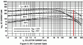
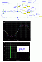
The original does have a pull-up problem. The 680r resistor, divided by the hFE of Q1, makes it act like there is 6.8 Ohms in series with pull-up, so it barely gets over half way to the 42V rail.
The revision with PNP driver is *unity* gain, but the pull-up is a shade worse due to 820r resistor. Does have good damping. I think Broskie has written on this.
Up to that point THD is not excessive. Not point-oh-oh-oh certainly, but not a stinker.
The revision with PNP driver is *unity* gain, but the pull-up is a shade worse due to 820r resistor. Does have good damping. I think Broskie has written on this.
Up to that point THD is not excessive. Not point-oh-oh-oh certainly, but not a stinker.
Unfortunately LTspice on my Mac is a disaster, Ican not make it work well, I can not simulate anything.
alephotos, why don't you convert it into a JLH 1969 amp?
There's only a few more parts and it will both answer all the criticisms here and still keep a good measure of the 'sound' you probably like.
If you want to make it sound even better while keeping the 'nice sound', try the cheapo SMPSs I recommended.
This is a tried & tested design with loadsa info on the pitfalls. A new circuit, even by the gurus here, are untested and may turn round & bite you.
...answer all the criticisms here...
Why should he do that??
I suspect that when he tries to set up a "matched" duplicate for stereo, or tries to drive some different speakers, he will learn why most amplifiers are a wee bit more than this. But until that happens, I still say it looks like fun.
😀 I never suspected PRR could be so evil !!I suspect that when he tries to set up a "matched" duplicate for stereo, or tries to drive some different speakers, he will learn why most amplifiers are a wee bit more than this. But until that happens, I still say it looks like fun.
This circuit has a passing resemblence to my first 'power' amp. It was from a Philips EE20 kit and I was 7. It had 3 Germanium transistors and the creme de la creme circuit was a Class A amp using all 3.
I discovered that increasing Iq (I didn't know what it was called then) made it sound much better. I took this to its logical conclusion and let out the Holy Smoke. 😱
This was a serious matter cos in those days, transistors came in little cardboard boxes and cost a week's pocket money each for a kid. 🙁
A bit later, I found out that you could recover good devices from old broken transistor radios which was a huge saving 🙂
No holy smoke, the circuit at post 1 is playing happily, even if it's just an exercise that plays happily. I can not duplicate the channel because the transformer is not very powerful
Hi alephotos
I thought you said the PT is 350VA ? That is basically 350W. If the amp is pulling 2A at 42V that is 84W of heat and there should be lots of available power from the PT.
The amp is a lot like a true Lin amp but with a JLH output stage instead of a symmetric EF. The Lin is inverting and has DC feedback around the input BJT to centre the output DC. Like PRR said, the trick will be getting two channels to have the same gain.
Even if a sim shows that THD is bad above 1W, the fact it is functional is a big enough thrill for most builders upon powering something up. The fact it does not sound obviously distorted is the next thrill. The fact it keeps working is the next thrill. With typical speakers, 1W will be too loud to stay in the room, so if all the listening so far has occured at a few tens of mW or hundreds even, it is still great success.
For reference, in high school we built JLH amps as stereo running from a 36V 2A PT that got quite hot powering two channels. All the circuit values were stock per the revised article (RF updates added).
...a lot like a true Lin amp...
I don't see any Lin at all, except it is made of transistors.
...Even if a sim shows that THD is bad above 1W
Why do you keep saying that? Have you worked it out?
The gain function is mostly about hFE linearity. If hFE were dead-linear, THD would be quite small.
My demo sim only has small parts. So I scaled all impedances up by factor of 10, in hopes of not getting on the down-turn of hFE. I missed a little.
The primary result is it not coming anywhere near the supply rail. Q2 base resistor reflects through hFE as a series resistor with the load. For my values, hFE Q2 is 165, RB is 6800, so Q2 acts-like 41 Ohms, which severely limits the pull-up possible in 80 Ohm load. This is a real waste of heat.
If we stay short of that, there's no gross distortion to 12V peak output, which would be over 8 Watts rather than "1W". Yes, it sims as 4%, mostly 2nd. This is because the available part is already in hFE decline. The parts on alephotos' drawing have much flatter hFE curves and the bias probably hits their flat-zone, so THD will be lower.
Attachments
The transformer war recovered from a no-working amplifier, the 350 VA power I calculated by measuring the nucleus roughly. Having many secondary surely the power is a little less than 350 VA on the line I'm using, I would not want to destroy it because I need another AB amplifier, however I'll try, the transistor are matched and come from the same non-working amplifier. The adjustment of VR1 to get 1/2 V before the out capacitor I think has a fundamental role, at least I think.
Hi PRR
Everything except the wiring of Q3 is like an original Lin, which used a PNP there tied to C of Q1.
What people often call a Lin is a true Lin with a diff-input stage added. Some say that is Thompson (sp). In between the two was a single input transistor added as in Bailey and others.
Everything except the wiring of Q3 is like an original Lin, which used a PNP there tied to C of Q1.
What people often call a Lin is a true Lin with a diff-input stage added. Some say that is Thompson (sp). In between the two was a single input transistor added as in Bailey and others.
Everything except the wiring of Q3 is like an original Lin, which used a PNP there tied to C of Q1....
I have not seen a complete bibliography of "Lin"; if someone has one I would love to see it.
Lin seems most associated with *complementary* techniques. Because he could not get big devices of both genders, he is also known for quasi-complementary. The attached is not his oldest paper but seems to be (plus similar work in Transistors I) his best known.
There's only so many ways to connect 3-leg parts, so the jigsaw has to look similar. But the 1956 work is very much class B. The infamous JLH and alephotos' plan can only work class A.
Attachments
- Status
- Not open for further replies.
- Home
- Amplifiers
- Solid State
- minimal class a amp

