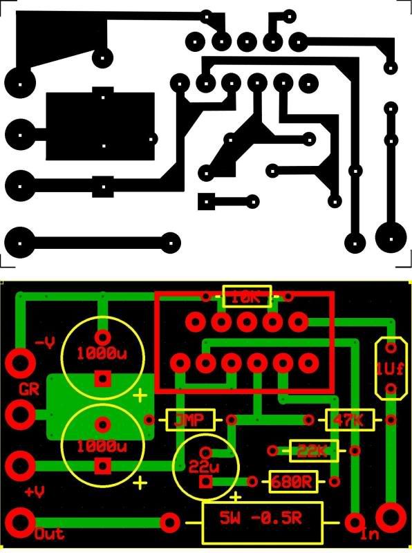
Hi Folks , I just thought I would share a simple Single sided small LM3886 PCB with you .....
The version is pretty much the Datasheet implementation with no special features or components...
It measures 2 in x 1.3 in and has a single Jumper and is easy to etch at home ....
I just built one and it works perfectly and has no hum even though the Power and signal grounds aren"t seperated .....
Just simple , quick, and dirty .....
Cheers

You can always replace the jumper with a small resistor to separate the grounds.
The 5W 0,5R resistor is only necessary in parallel applications. Rating and resistance are too big and it touches Ci, which does not like heat.
Rin should be connected between Cin and IC, not between input terminal and Cin. The way you laid it out, the filter frequency depends on the IC's input resistance instead of Rin.
Where is Rb?
Space for Cc against Rf disturbances, Rsn/Csn against oscillations and L/R against reactive loading should be provided.
You should also state the biggest possible voltage rating for that design, which will be limited by the size of the 1000 µF capacitors.
Well I never claimed it to be a Good design , it is at the very best Functional .....
I Forgot about Rb so I soldered it on the bottom of the board but worked the same without it ......
😀
I Forgot about Rb so I soldered it on the bottom of the board but worked the same without it ......
😀
Attachments
Minion:
😀
Might oscillate, if the speaker out is so close to the input, and the absence of "Zobel" might make it worse or good as an AF oscillatorWell I never claimed it to be a Good design , it is at the very best Functional .....
😀
Kay:
can't say with a single glance 😀
but seems to be colorful !!
😀
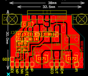
Efficient design (better use of copper)
you like this?
can't say with a single glance 😀
but seems to be colorful !!
😀
Efficient design (better use of copper)
- Status
- Not open for further replies.
- Home
- Amplifiers
- Chip Amps
- Mini-LM3886 PCB 4 You !!!