Hi everybody,
I just finished building my first digital audio project, and I thought
I'd submit it for a public review. It is a small and relatively simple
DAC built around latest Burr-Brown/TI chips, with a few design choices
that are uncommon, but seemed interesting to me.
Here are the specs:
Chipset:
Digital part is pretty much datasheet implementation, except for fairly
elaborate power supplies. Analog circuit is more interesting, with
passive I/V conversion and low-pass filter followed by fully
differential gain stage. The whole thing fits on a 8x10cm PCB, and can
run from 6V battery power. I assembled and tested a prototype, and it
works. Datastreams up to 96kHz/24bit are supported, and the noise floor
is low (below that of my amplifier). Subjective sound quality
evaluation will take some time, though...
So, what do you guys think?
P.S. I have a few spare PCBs if anyone is interesting in building this...
I just finished building my first digital audio project, and I thought
I'd submit it for a public review. It is a small and relatively simple
DAC built around latest Burr-Brown/TI chips, with a few design choices
that are uncommon, but seemed interesting to me.
Here are the specs:
- 96kHz/24bit Toslink input
- balanced output (2.47Vpp full scale)
Chipset:
- DIR1703 DAI receiver
- PCM1730 advanced segment DAC (Delta-Sigma)
- passive RC-L-RC I/V converter and 3rd order Bessel filter
- THS4131 fully diferential amplifier in output stage
- TL431 shunt regulators in digital supplies
Digital part is pretty much datasheet implementation, except for fairly
elaborate power supplies. Analog circuit is more interesting, with
passive I/V conversion and low-pass filter followed by fully
differential gain stage. The whole thing fits on a 8x10cm PCB, and can
run from 6V battery power. I assembled and tested a prototype, and it
works. Datastreams up to 96kHz/24bit are supported, and the noise floor
is low (below that of my amplifier). Subjective sound quality
evaluation will take some time, though...
So, what do you guys think?
P.S. I have a few spare PCBs if anyone is interesting in building this...
Attachments
To peranders:
Thanks... I don't have a digital camera, so no pictures for now. Maybe some day...
To Ric Schultz:
I thought about it, but felt that passive filter will create less problems than it absence would cause. PCM1730 is a delta-sigma DAC, after all, and there is a fair bit of out-of-band noise on the current output (although BB says much less than single bit modulators). Feeding this into feedback loop is asking for trouble, even with such a fast chip as THS4131... Eliminating the passive filter and doing active I/V conversion with THS4131 will bring the cost and board space down by a factor of almost two, so it is certainly an option...
BTW, I am using Panasonic SP-Cap specialty polymer electrolytics for bypass duty, since they have low impedance at high frequencies.
Sorry, still no photo... Although I have a digital camera now, so I can take one if you really want to see it ") .
.
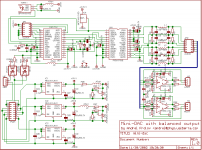
I have build another DAC with balanced output since then, which I like better. It uses better digital filter and DAC chips (NPC SM5847/SM5865). Output stage is still THS4131, but power supply has been significantly improved. Photos and schematics are posted in this thread.
I am currently re-designing my NPC DAC to improve jitter rejection. I am going to reclock digital filter and DACs from local buffered low-jitter DCXO (CY23FS04) locked onto the recovered interface clock. Cypress promises 55db of jitter reduction at 1.7kHz, which is a lot.
.I have build another DAC with balanced output since then, which I like better. It uses better digital filter and DAC chips (NPC SM5847/SM5865). Output stage is still THS4131, but power supply has been significantly improved. Photos and schematics are posted in this thread.
I am currently re-designing my NPC DAC to improve jitter rejection. I am going to reclock digital filter and DACs from local buffered low-jitter DCXO (CY23FS04) locked onto the recovered interface clock. Cypress promises 55db of jitter reduction at 1.7kHz, which is a lot
.andrei said:Hi everybody,
I just finished building my first digital audio project, and I thought
I'd submit it for a public review. It is a small and relatively simple
DAC built around latest Burr-Brown/TI chips, with a few design choices
that are uncommon, but seemed interesting to me.
Here are the specs:
- 96kHz/24bit Toslink input
- balanced output (2.47Vpp full scale)
Chipset:
- DIR1703 DAI receiver
- PCM1730 advanced segment DAC (Delta-Sigma)
- passive RC-L-RC I/V converter and 3rd order Bessel filter
- THS4131 fully diferential amplifier in output stage
- TL431 shunt regulators in digital supplies
Digital part is pretty much datasheet implementation, except for fairly
elaborate power supplies. Analog circuit is more interesting, with
passive I/V conversion and low-pass filter followed by fully
differential gain stage. The whole thing fits on a 8x10cm PCB, and can
run from 6V battery power. I assembled and tested a prototype, and it
works. Datastreams up to 96kHz/24bit are supported, and the noise floor
is low (below that of my amplifier). Subjective sound quality
evaluation will take some time, though...
So, what do you guys think?
P.S. I have a few spare PCBs if anyone is interesting in building this...
How much for the PCB's Andrei, I would like to try it out.
Regards
Anthony
Member
Joined 2002
andrei, do you see any ill effects of the finite output impedance of the DAC? Have you done tests with pure input tones and then looked at the output spectrum to test for harmonic errors?
I'm asking because I plan to do something quite similar to your design with the PCM1794.
By the way, how big a role do the power regulators play? On my board (which will hopefully get here in the mail soon) I have just put down a 337 or 317 for each power rail I use. I use separate regulators for analog and digital with a common wire feeding all positive regulators.
Greetings,
Børge
andrei, do you see any ill effects of the finite output impedance of the DAC? Have you done tests with pure input tones and then looked at the output spectrum to test for harmonic errors?
The short answer is no and no. I don't have spectrum analyzer that is sensitive enough. Anyway, I am not worried about harmonic distortion, since my power amp (single-ended triode, no feedback) has high THD (which does not stop it from sounding better than all the solid states ones I heard
).I'm asking because I plan to do something quite similar to your design with the PCM1794.
Another thing to consider is to use step-up audio transformer instead of inductors. You get many benefits: leakage inductance of the transformer becomes a useful element in the low-pass filter, you get low-noise and low-distortion voltage gain stage where it counts, output is galvanically isolated and could be referenced to ground (instead of 1/2Vcc DAC bias), and common mode rejection is superior. The downside is that a good audio transformer is going to cost you.
By the way, how big a role do the power regulators play? On my board (which will hopefully get here in the mail soon) I have just put down a 337 or 317 for each power rail I use. I use separate regulators for analog and digital with a common wire feeding all positive regulators.
Noise in equals noise out. You can get away with noisier supplies using differential topology due to higher PSRR, but still...
Member
Joined 2002
is this dac for only one kinda of cd player. ? can i use it in my new cd player. ?
It is a stand-alone DAC with Toslink input. If you CD player has optical digital output (which it probably does), you could use it. As usual, YMMV.
- Status
- This old topic is closed. If you want to reopen this topic, contact a moderator using the "Report Post" button.
- Home
- Source & Line
- Digital Source
- Mini-DAC with balanced output