Hi all,
Recently I rebuilt my Mini Aleph and ran into stability problems. The amp runs for around 3-5mins then stops working. Probing the outputs of the amplifier shows that upon turn on, the DC bias is low and as the amp heats up, the DC bias starts to swing wildly and eventually swings to one of the power supply rails. Previously before the rebuild, the amp ran well without such problems, not sure what could have caused this problem this time round.
I am using Brian-GT boards, running a PSU rail voltage of +/-16V and have a CRC filter in the PSU.
Tried changing the heatsink to a very huge one and the same problem still remains. Changed the output devices and IRF9610 but the same problem remains too. Really at a lost as to what is happening. Any help would be greatly appreciated! 🙂
Cheers
Attachments
damn schematic could help
also - try puttin' 2pcs of 1nF (anti-oscillation caps) per channel - look at older schmtcs of Aleph 3 and 30 , not sure exactly which one , in any case - older original ones
also - try puttin' 2pcs of 1nF (anti-oscillation caps) per channel - look at older schmtcs of Aleph 3 and 30 , not sure exactly which one , in any case - older original ones
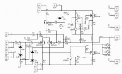
Oops, my bad. Here is the schematic that was used for this build.
R8 and R13 have precision potentiometers for adjusting of DC offset and bias. I am trying to make them run at >1A.
Regarding the 1nF capacitors, are they the ones that I highlighted in green in the aleph30 schematic that is attached? Tried comparing both schematics and there are other 0.47uF capacitors that are in parallel with the 220uF capacitors too. Should I add those in too?
Thanks for the help!
Attachments
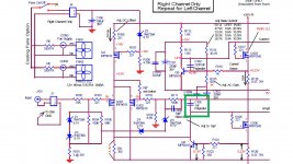
counting that everything is connected as predicted , and you didn't make some mistake in resistor values , try putting 1nF caps marked as C105 nad C102 in Aleph 30 schematic
I would leave R8 as is in schematic and replace R18 with 500R trimpot, speaking of Brian's
one important question (which can give info is there some systematic mistake) - is same misbehavior with both channels ?
be sure that output mosfets are mounted flawlessly - there are no burs on heatsink (making contact through mica when hot) and properly tighted
It isn't a systematic error cause I experience this problem in both channels.
May I ask why it is better to leave R8 and change R18 to a 500R trimmer? Is it to maintain the bias current of the devices?
I tried adding c105 as per aleph30. C102 was originally there in the circuit. Ran it for 15mins and so far so good! Will run it longer and monitor it's stability. Thanks Zen Mod!
it can be part issue if just one channel is in question
if both channels are misbehaving , that's systematic issue/mistake/culprit - common for both channels
R18 instead of R8 , just to be sure that you didn't current starved input LTP
if both channels are misbehaving , that's systematic issue/mistake/culprit - common for both channels
R18 instead of R8 , just to be sure that you didn't current starved input LTP
It seems that the amp can operate now. I swapped R8 back to its original value and changed R18 to a 500R trimmer to adjust the dc offset. It seems like at certain trimmer settings, the amp will oscillate wildly around +/- 500mV offset and eventually settle at around 200mV DC offset. All these while, the amp is still able to play music but it makes some static noise as it oscillates. If I try to adjust R18 to reduce the dc offset, the amp would sometimes have no effect on the output dc offset or it would repeat those wild oscillations again.
I suspect that the amp might be operating at the point where Q2 is just about to turn off as R18 value may be too high. Could that be the case?
Also, I noticed that the amp has a large and slow turn off thump. Any suggestions to reduce it?
Thanks!
I suspect that the amp might be operating at the point where Q2 is just about to turn off as R18 value may be too high. Could that be the case?
Also, I noticed that the amp has a large and slow turn off thump. Any suggestions to reduce it?
Thanks!
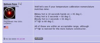
Ahh it probably is lower than 45 cause I can place my hands on the heat sink for way more than 10s. I'm running forced convective cooling though.
up Iq to 55C at heatsinks
that will lead to somewhat higher OLG , so little more feedback , hopefully putting it in non oscillating area
that will lead to somewhat higher OLG , so little more feedback , hopefully putting it in non oscillating area
tried to run it at a higher temperature but the same issue is still present.
Was just wondering, I noticed that on my board, Q1, Q2 and Q3 runs pretty warm, would say close to 40 degrees. Is it supposed to run that hot? Looking through the schematics I would think that only 10mA flows through it so it should not be warm at all. Any idea?
Was just wondering, I noticed that on my board, Q1, Q2 and Q3 runs pretty warm, would say close to 40 degrees. Is it supposed to run that hot? Looking through the schematics I would think that only 10mA flows through it so it should not be warm at all. Any idea?
Swapped out Q1 to q3 for new and matched ones. Turns out the problem are these devices; they were semi functional and would operate abnormally when hot...
I have yet to measure voltages across R8 and Z5 but the amp is now stable. Will measure these voltages to be absolutely sure later. Thanks Zen Mod for your help thus far!
I have yet to measure voltages across R8 and Z5 but the amp is now stable. Will measure these voltages to be absolutely sure later. Thanks Zen Mod for your help thus far!
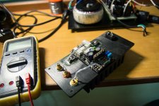
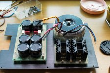
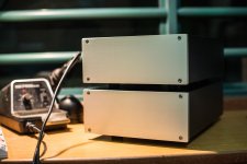
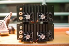
Thanks ZM for your assistance! Managed to complete building both channels today. Thought I would share some photos here 🙂
Attachments

- Status
- Not open for further replies.
- Home
- Amplifiers
- Pass Labs
- Mini Aleph Stability Issue