Hi
I have made a board for the Mini-A and would like to hear some opinions on the layout.
I have added protection diodes on the input and the possibility of bypass caps for the electrolytics. The board are two layer. The top layer hold the ground level and the bottom holds the signal and power.
Here's a picture of the layout. The actual films will be posted in a zip file when I decide not to change them any more (a day or so).
Attachments
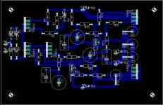

If this is the final board's size, I would place the output Fets as close to the edge as possible for direct mounting to the heat sinks. As it is now, wires are required.
Thomas,
In addition to putting the output devices closer the the edge of the board, I like to have the outputs positioned closer to the edge. I also don't like resistors placed vertically since it puts more strain on the resistors and the pcb. It wouldn't take up much more space with them positioned vertically. Also, you can get away without a heatsink for Q1 - Q3, but I would leave room for heatsinks, and possibly putting Q1 and Q3 on a shared heatsink (with insulators) for better thermal tracking. The only other suggestion that I have is that you could leave more spacing for the caps, in case you decide to try some exotic caps later. (there are only a couple used, so the cost could be justified).
skaara,
read the thread on the Mini-A here:
http://www.diyaudio.com/forums/showthread.php?s=&threadid=2001&highlight=minia
It is a creation by Grey ~9 months ago. Basically it is a small aleph with +-15v rails, drawing 1 A. It is a scalable design as are the rest of the Aleph designs.
--
Brian
Finished PCB's for Mini-A
Peter, Brian
Thanks a lot for your input! 😀 😀 😀
So, here are the much cleaner layout.
Featuring:
More room for power resistors, room for heatsinks on Q1-Q3, output devices on edge. Option for protection diodes on input ( 9.1V zener). Multiple holes for the cap of your choice.
The board are two layers, the top is the ground level. Of course you could easily use a wire instead, because there are only five or so ground connections.
Note: you have to download all three parts of the zip. Final size =202kb. Print films are in PDF format and should print correct size at 600 dpi.
I must say that I haven't build the boards yet, so they are UNTESTED. Don't kill me if they don't work, kill your cat.
Good luck bulding!
I have put up a website for the file. This is the 'original' file I intended to post here, but could not because it's too large. I'm truly sorry about the mess with the three invalid files I posted at first.
I intend to make an other version, moving the output devices around the corners, so seperate heatsinks can be used on each side of the PCB, one for each o/p device. The reason for this is I got a stock of smaller heasinks I would like to use. I will post my results here.
The link for downloading my files are: http://members.fortunecity.com/minialeph/
(There are one popup window 😡 )
May I suggest 2 things
1-using irfp044 as the ouptut devices, they are much better in just about respects. Maybe you could provide dual pinouts.
2-put the CS and the diff pair Q's closer and on the same line so one can thermally couple them with a thin Al strip.
1-using irfp044 as the ouptut devices, they are much better in just about respects. Maybe you could provide dual pinouts.
2-put the CS and the diff pair Q's closer and on the same line so one can thermally couple them with a thin Al strip.
Hi Thomas,
in another thread I asked you to send me the layout.
Well, I sat tight and now you´re already finished.
Would you mind sending me the Eagle files schematic+layout.
I wanna build the mini-a and probably edit it for my mini-heatsink.
Thanks in anticipation
PS.: Keep us informed about the sound. (And some pics please)
Grataku:
Moving Q1, Q2 and Q3 closer is probably a good idea, thanks.
I think the option for to-247 style transistors sounds like a sound thourgt. Afterall, in Grey's original introduction it sounded like this was meant to be buildt with spare parts you allready have, so a few possibilities aren't bad at all. 🙂
Jonesd:
You can have the schematic file, I will put it up on my site. Afterall, this is only a replica of Greys work, and doesn't represent any independent thourghts or hard work from me. But the PCB layout represent many hours of work, and doesn't give away. I'd rather make the alterations you want, and post it on my site, so others may use it too. I would like the PCB's to be 'mine', you see. I would love to hear about your mini-sinks. Maby you could send me a picture or drawing. I, myself will be using one heatsink on each output device, so a version with the output devices on each side of the PCB will be put up for dl before the week-end.
Others:
The layout will be updated this week and there will be a new one with the output devices on each side, so you may choose to use one, or two smaller heatsinks. This will be done this week also.
The site as it is now, a little dull. It will be updated with info/pictures of my own project as it comes along. I will inform this board when anything major happens. About 2-4 weeks or so is realistic.
Thank you Thomas,
I´ll download the schematic file.
With the layout... I can well understand if you won´t give it out.
I´m gonna do it and change it anyway.
If I get some nice results I´ll send you my version.
Before I have to finish some other amplifier.
The heatsink I was talking about is a little "tube" with forced convection (right words for this??). That little tube is only 40*40*100 mm (sorry I don´t know the inches) but with a fan it´s quite effective. You can get those real dirt cheap (in comparison to Fischer Elektronik) at ELV in germany.
You can get it in a bigger version likewise.(60*60mm)
I can send you pics if you´re interested.
I tried to download the eagle schematic but it´s either not found
or it seems to be corrupt.
The download manager (I´ve tried without was well) says it appears to be a html-file.
Thomas, would you please check that?
TIA
or it seems to be corrupt.
The download manager (I´ve tried without was well) says it appears to be a html-file.
Thomas, would you please check that?
TIA
joensd said:Thank you Thomas,
I´ll download the schematic file.
With the layout... I can well understand if you won´t give it out.
I´m gonna do it and change it anyway.
If I get some nice results I´ll send you my version.
Before I have to finish some other amplifier.
The heatsink I was talking about is a little "tube" with forced convection (right words for this??). That little tube is only 40*40*100 mm
(sorry I don´t know the inches) but with a fan it´s quite effective. You can get those real dirt cheap (in comparison to Fischer Elektronik) at
ELV in germany.
You can get it in a bigger version likewise.(60*60mm)
I can send you pics if you´re interested.
1. Thanks for understanding. 😉
2. I know 2 types: natural and forced convection.
3. Thanks for the link to ELV. I'm allways looking around for something usefull.
4. We use the metric system here in Denmark too, neighbour. 😀
5. Please send me the pics. My E-mail is kobbertraad@hotmail.com
joensd said:I tried to download the eagle schematic but it´s either not found
or it seems to be corrupt.
The download manager (I´ve tried without was well) says it appears to be a html-file.
Thomas, would you please check that?
TIA
Yearh, I know. I was updating the site a little, when my computer froze. It was late (past midnight) and I didn't bothered to reboot, but went straight to bed. The links to Pass Labs and here don't work either.
I'm learning the html 'on the fly', so right now i'm fighting to make everything work.


- Status
- Not open for further replies.
- Home
- Amplifiers
- Pass Labs
- Mini-A PCB's