GRollins said:Says here:
OT- But, if you are cleaning up after sheet rocking, just water does wonders. A floor polisher and water should get down to the concrete fast. A scraper may be needed to remove oil base paint overspray.
Good luck, I pulled up carpet and glued down Bruce Brazilian cherry in three rooms last year. Cleaning the slab and prep was the hardest part.
George
"Contains Sodium Metasilicate Pentahydrate and Sodium Carbonate. Avoid contact with skin, eyes, and mucous membrances..."
Actually, it occurs to me that I'd better stop or Rodd will get it in his head that I'm encouraging newbies to snort this junk up their noses and SinBin me again. Harrumph! Don't ask me what I think of the way the site's being run...I might answer.
HCl (aka Muriatic Acid) is useful stuff and I happen to have a gallon on hand, but what I don't have is good ventillation. My Mad Scientist Laboratory is in the basement and there's precious little ventillation down here, even with fans. This stuff doesn't make noxious fumes. Add to that the fact that it's old and I want to use it up to clear more shelf space and it seems like a good time to scrub.
As for the hands and knees part, I've got to get up under built-in shelving and such. Elseways, I'd use a pushbroom like I did in the brewery.
Two output devices, eh? Now, that's interesting.
Okay, here's what I've been thinking. I did Ariels and ME-2s for the 5.1 AV system upstairs. Well, actually it's 5.3, but let's not get picky. Anyway, the point is that those tweeters come in pairs, right? I couldn't stand it. I went ahead and bought woofers and stuff to go with the spare tweeter. So I've got this center channel speaker up front...and a spare ME-2. In which I just happened to wire the drivers out separately so as to be able to get to all three drivers. (Yes, I know what's-his-face likes the crossover mounted externally, but I didn't wire the woofers in parallel until I got outside the box in case I wanted to do something kinky, like give each woofer its own amplifier.) So, supposing we were to put a Mini-A on the tweeter and an Aleph-X on the bottom. Which is part of what led to the whole Mini-A/Aleph-X thing anyway.
Well!
Okay, then I started thinking about the bottom end, which is a little on the puny side. Then I turn around and...lo...there are those nifty old KEF B-139s, just begging to go in and carry the load from, say, 150 Hz on down. So then we go for another Aleph-X, or perhaps just a straight X. Now we're tri-amped.
Then, just to be really excessive, what about another B-139 below that (i.e. roughly 40-50Hz, which is where they poop out unless you put them in a transmission line), crossed over with an LP filter at about 20Hz, making that the subwoofer.
An LP at 20? Huh? I thought you wanted something that would cross over at 50!
No, I'm not nuts, despite what some have tried to tell you.
Suppose we use a driver--any driver--in a sealed box that's -3 @ 50. Coming in from the right, we have a straight line at 200...100...a little droop...then -3 dB at 50...then a typical 12 dB/oct rolloff. Just for a moment pretend that it's not a driver, it's a high pass filter. What would happen if we added a low pass at 100? We'd get a bandpass, right? It'd be -3 dB at 50Hz (HP) and -3 dB at 100Hz (LP) and kinda-sorta flat in between. In reality, the droopiness would make it rounded, but you get the idea.
Take it one step further. Slide that low pass filter down to some arbitrary frequency, say, 20 Hz. Put on your thinking cap and we'll do this in three parts.
First, the under-20Hz region. Add a flat line (the pass band from the low pass filter) and a sloping line (the falling response from the driver), and what do you have? Well, you've still got a falling response below 20 Hz. They sum to a low pass.
Next, the above 50 region. Add a flat line (in this case the driver response), and a sloping line (the low pass slope from the filter) and what do you get? Right. A high pass function. The response is falling.
Now here's what drives people nuts. Between 20Hz and 50Hz, you've got two falling responses, one HP and one LP. One slopes from right to left and the other one from left to right. What happens when you sum those two? A flat line.
We just took a driver that effectively stops at 50Hz and made a subwoofer out of it. Without a boost circuit. Without oscillations. Without feedback, feedforward, or other manipulations. The really cute thing about all this is that the driver still cuts out before it gets to the really ugly subsonics. It's flat (we're assuming that the driver/cabinet combination has a smooth rolloff) in the middle. And it rolls off nicely in time to meet the 'real' woofer. All with one, count 'em, one crossover slope! Less phase shift. Less circuitry. Automatic matching between the woofer and the subwoofer in tonality and crossover point.
Neat.
Need I say Rushmore?
Grey
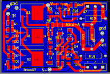
I saw your mini-A board, and decided to make a try at making one. I am using surface mount components for my other projects, so I decided to use surface mount resistors and caps for this mini-a. The resistors will be 1210 sized 1/4w, and the caps will be smaller film, and polymer electrolytics. I kept the larger resistors as the 3w panasonics.
Any suggestions for improvement? The board size is 3" x 2". The bottom layer is mostly ground plane, along with thicker voltage traces. I tried to cross all traces at perpendicular angles to avoid crosstalk. I am debating whether to remove the ground plane, or possibly make it solid, instead of crosshatched.
--
Brian
Attachments
Yeah, water is good for cleaning concrete, but adding stuff to it helps. At any rate, it's done. Now I get to see how much stuff I can cram into one 8' x 20' room and still move around. I've got two whole shelves taken up with variations on OTL tube amps alone. Need to finish a few things and make room for new ideas.
What is this...a race to see who can make the smallest Mini-A? Jeez, the next thing you know, NASA will be sending up miniaturized versions to use on the space station.
Maybe IRF could be talked into doing a Mini-A-on-a-chip. Just add heatsink and power supply.
Grey
EDIT: Something I guess I didn't make clear--the floor was filthy before I even began. All kinds of yukky-mucky things on the floor.
GRollins said:What is this...a race to see who can make the smallest Mini-A? Jeez, the next thing you know, NASA will be sending up miniaturized versions to use on the space station.
Maybe IRF could be talked into doing a Mini-A-on-a-chip. Just add heatsink and power supply.
After all, you might see a version of the mini-A buldt into a pepsi can.

Brian,
I'd like to see 5 of those in one box for HT! 🙂
would be neat to see a finished stuffed board of this.
cool.
I'd like to see 5 of those in one box for HT! 🙂
would be neat to see a finished stuffed board of this.
cool.
A couple questions about the Mini-A:
1.) Is the IRFP044 the best choice for the output devices?
2.) What voltage capacitors are needed for C1-C3 (electrolytics).
3.) Are there any improvements to the schematic that I used for the layout?
I should get boards made for myself made in a couple of weeks.
I want to make a small stereo Mini-A.
--
Brian
Very nice
1. Add a 1uf cap across D1. That's from the how to improve an Aleph thread.
2. More spots for output resistors. Will the board get hot from the surface mount parts?
3. Inputs for R15 and R16 off the board incase they want to double up on the outputs.
1. Add a 1uf cap across D1. That's from the how to improve an Aleph thread.
2. More spots for output resistors. Will the board get hot from the surface mount parts?
3. Inputs for R15 and R16 off the board incase they want to double up on the outputs.
MikeW said:Very nice
1. Add a 1uf cap across D1. That's from the how to improve an Aleph thread.
2. More spots for output resistors. Will the board get hot from the surface mount parts?
3. Inputs for R15 and R16 off the board incase they want to double up on the outputs.
Thanks for the suggestions. I added a cap across d1, named C7, and also added some mounting holes. I don't expect the board to get too hot from the surface mount parts. I think that the only parts that will get real hot are the 3w resistors, and the output devices, which can both be lifted off the board.
As for expandability, I added extra pads for R15/R16, for off-board expansion. Did I do it the correct way?. I am still thinking about the extra output resistors, and might make holes to mount an additional 3 more, under the board.
I have attached a picture of revised layout. Let me know what you think.
Thanks again.
BTW: Do you know what voltage caps are needed for C1-C3 (electrolytic). I don't think they are seeing too much voltage. Do you know the minimum required?
--
Brian
Attachments
Member
Joined 2002
Would you take out R15 and R16 and wire them p-p to one of the many output MOSFETs? Jumper R18 and R19 and run the Alpeh output boards?
I think 35 volts shoud be good for most designs. You could probably get away with 16 volts for the mini. Pick a package size that has the 220uf. 16 volt and 100 uf. 35volt the same size and double up on the pads. It looks like there is room.
I think 35 volts shoud be good for most designs. You could probably get away with 16 volts for the mini. Pick a package size that has the 220uf. 16 volt and 100 uf. 35volt the same size and double up on the pads. It looks like there is room.
- Status
- Not open for further replies.
- Home
- Amplifiers
- Pass Labs
- Mini A board
