Absolutely fantastic!
I'm curious: It's been stated that the power output is well below 40W/ch stock. What do you think is the power output?...
They feel massively powerfull! Like a V12 sports car.🙂
Here is a 20V/8ohm (50 watts) 1kHz sine with 8R load with stock-settings ("with GNFB") and with another setting (CFB = cathode feedback):
An externally hosted image should be here but it was not working when we last tested it.
At 18V (40W/8R) the sine looks like it should be. But you can see there is dynamic headroom above that if higher distortion at signal peaks is allowed.
At bass the output power is somewhat different story, as it is always. At 20Hz the OPT gives around 10Vrms with ok looking sine, but the "acceptable" amount of distortion at low freqs is also higher because it does not sound resentfull. I think they have very ample reserve of even the lowest of the low notes. The OPT is remarkably good, it has very good HF extension for it's size and bass reserve.
Full 40W power bandwidth at 20Hz is ridiculously hard to achieve with SETs.
Here is little over 10VRMS @ 20Hz with stock settings, except the GNFB is bypassed in both:
An externally hosted image should be here but it was not working when we last tested it.
These scope measurements were done at the beginning. After this I have removed cathode bypass capacitors of the AX/AU7, which linearized the amp considerably (and dropped gain 7dB IIRC). I have also removed the 200R grid resistor between the 300B and 805, which also linearized the amp further. I have done measurements with all these mods with sound card to be able to see better into the harmonics distribution etc.
As of now, the amps are VERY linear imo. I actually think these might among the best measuring non-GNFB SET amps out there, at any price.🙂
Like I said, I have bypassed the global negative feedback, added CFB around the OPT, removed the cathode bypass caps of AX/AU7, and removed the grid resistors of 805. With these settings:
1) At 2.83V the H2 is around 0,1% or slightly under that (and <0,1% below that)
2) At 5V the H2 is around 0,18%
3) At 10V the H2 is around 0,6-0,7% (my sound card L-pad settings cannot measure above 10V at this point without overloading the input)
The amp is now somewhat more linear completely without GNFB than it was as stock, with approx. 11-13dB of GNFB.
Here is 5V/8R with current settings, no GNFB:
An externally hosted image should be here but it was not working when we last tested it.
Last edited:
Thank you kindly, Legis! This is perhaps the most complete power analysis I've seen on this amp. It answers many questions on the legitimacy of the stated numbers. I'm convinced that this is a tremendous value based on your measurements. Please keep us posted as your amp continues to evolve.
However, I don't have the skills necessary to venture into the unkown of modifications other than basic DIY, swapping tubes, and coupling caps. Which leads me to ask, what is your preferred choice of coupling caps?...
However, I don't have the skills necessary to venture into the unkown of modifications other than basic DIY, swapping tubes, and coupling caps. Which leads me to ask, what is your preferred choice of coupling caps?...
This was reported on the 211 amp model, seemd the 805 amps was measured w/38W by a magazine.Absolutely fantastic!
I'm curious: It's been stated that the power output is well below 40W/ch stock. What do you think is the power output?...
However, I don't have the skills necessary to venture into the unkown of modifications other than basic DIY, swapping tubes, and coupling caps. Which leads me to ask, what is your preferred choice of coupling caps?...
I have not decided yet. Maybe the new Jupiter Wax & copper foil although I have not used them before. I usually tend to agree with the Humble Home Made Hifi's capacitor test on those caps which I have tested in my system.
Legis,
This amp use hard wiring?
What do you think is the wiring gauge?
Thanks
Like you know from pictures around the net, for the most part the different components are soldered directly to each other without any additional wire between them.
Where there is wire, it's thickness varies based on how much current the specific wire has to carry. RCA connectors have tiny wires, power transformer has thicker ones. Their thickness seems to be adequate IMO. I would not be worried that even the filament wires of the 805 (3.25A) were too small, because they are so short.
Some random current density spec in power transformers is 3,5A/mm2. I would say the 805 filament wires are at least that what come out of the transformer, but I don't know how thick the wire inside the transformer winding is. It does not get exceedingly hot even after 10 hours of usage, temps are propably in the same region where my previous A-class transistors amps cooling fins, ie. 55-60deg, which is very ok for a power transformer (only 30-35deg above the surrounding/ambient air's temperature).
Hi Legis,
Iam curious on how the manufacturer managed to get good SQ from this amp.
Its a pretty basic amp, dont have two power on switches, dont have soft start,
dont have choke, trafos are not M6 and it even have a power VU at output.
It have nothing extraordinary, only thing special is the hardwiring assemblage.
What could be theh source of the good sound? The OPT?
Last edited:
Hi Legis,
Iam curious on how the manufacturer managed to get good SQ from this amp.
Its a pretty basic amp, dont have two power on switches, dont have soft start,
dont have choke, trafos are not M6 and it even have a power VU at output.
It have nothing extraordinary, only thing special is the hardwiring assemblage.
What could be theh source of the good sound? The OPT?
The circuit is the key, of course. 🙂 Input stage, SRPP-stage, cathode follower driver and the dynamic and quite special sounding transmitting triode 805 as the output. The OPT is also very good imo and gets better after potting (better clarity).
I have read the Z11 lamination is the japanese equivalent to M6 lamination. Same material, only different name.
The amp actually has two stage power up. It has a relay that switches the anode voltage of 300B/12AU7/12AX7 at ~30 seconds after the initial power up. It does not have soft start but I have done one myself. This has nothing to do with SQ but tube life might be increased.
With stock circuit the amp is silent and does not necessarily need chokes in the supply to make it silent. But I will rework the PSU's (among other tweaking) naturally. BTW, now I'm playing the amps with 845 power tubes. I have gotten approx. 8Vrms out of the with 845 (6Vrms under 1% H2 distortion with zero global feedback). I have added a rotary switch that changes between different cathode resistors so I can change between 845, 211 and 805 as I wish. Tube roller's wet dream... 🙂
I don't believe the VU-meter does much harm to the sound. I have removed it (it does not read any electrical signal), but I kept the beautiful golden/yellow leds of the meter powered up from the filament supply of the 300B/2A3 (separated by large series resistor). My speakser are so sensitive that the meter was not visibly moving anyway. 😀
I short, I believe the circuit design, the tubes and the OPT is the source of the SQ in any given tube amp. In MC3008-A the circuit is easily tweakable with slight changes to circuit, audiophile components etc. of one's own desires because of the state of art point-to-point wiring. Maybe p-t-p wiring also sounds better than signal traveling through vibrating epoxy circuit board with tiny traces? 😉
Last edited:
Thanks for the nice report.
Do this MingDa amp use the Cary circuit??
Do this MingDa amp use the Cary circuit??
An externally hosted image should be here but it was not working when we last tested it.
Thanks for the nice report.
Do this MingDa amp use the Cary circuit??
An externally hosted image should be here but it was not working when we last tested it.
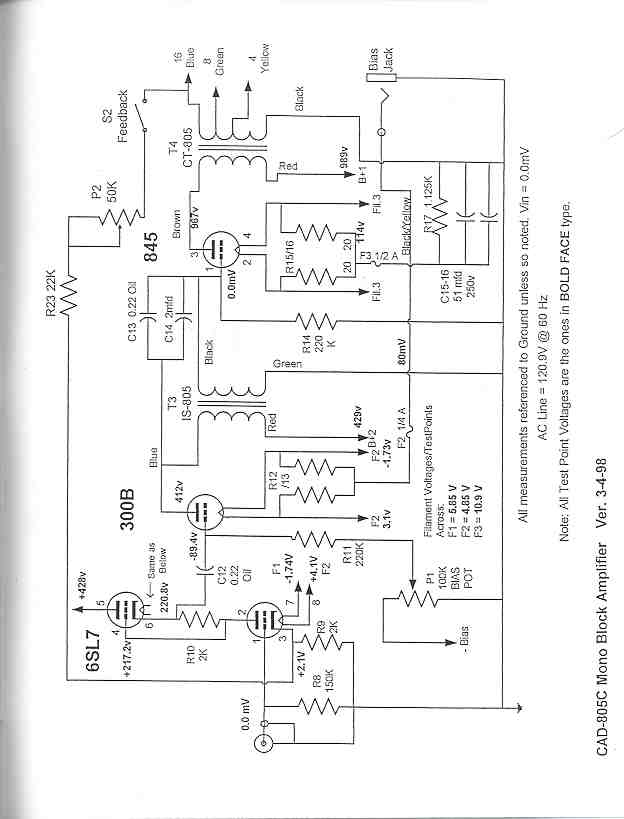
Propably there is some resemblance but clearly they are different amps. Cary has a switch to use different power tubes (805/211) and different pre stage with different tubes.
The Cary is not SRPP?Propably there is some resemblance but clearly they are different amps. Cary has a switch to use different power tubes (805/211) and different pre stage with different tubes.
Thanks.It is.🙂
So, as I suspect all these MingDa amps are descendants of Cary.
Thanks.
So, as I suspect all these MingDa amps are descendants of Cary.
Compare the schematics. Those two amps do not have anything else in common besides the SRPP 😀. SRPP is very commonly used stage.
I'd say these two models are totally different amps.
There is a second schematic?Compare the schematics. Those two amps do not have anything else in common besides the SRPP 😀. SRPP is very commonly used stage.
I'd say these two models are totally different amps.
Do you can post it?
So the Ming Da is a Mystery Amp to me;🙂

The Cary is IT coupled, notice the couple caps bypassed across IT. Probably for current dump because of the poor quality of IT?Thanks.
So, as I suspect all these MingDa amps are descendants of Cary.
- Home
- Amplifiers
- Tubes / Valves
- Ming Da MC-3008-A2 Mono Blocks