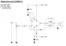
I build this 1 for subwoofer use. Sounds quit good with normal speakers but will have to see how they will drive subwoofers once I get them and build them - (Pass El-Pipe-O model with 8" drivers and 7ft pipe). I use 20,000uF / rail at moment. Some pics to follow later.
Attachments
wouldn't the 10k pot affect gain in the same way source impedance would affect gain. in other words, wouldn't the gain of the circuit be less then 10 for most cases?
It would.
JDdev, do the clasick IGC, but with FB resistors of 220k and 10k to gnd (plus 5k from your 10k pot the gain will always be mor than 10).
Greg
JDdev, do the clasick IGC, but with FB resistors of 220k and 10k to gnd (plus 5k from your 10k pot the gain will always be mor than 10).
Greg
i don't get what you two are saying?
his design looks alomst exaclty like mine which is based directly on the natsemi auxilliary amplifier refence design (i.e 10k pot, 1k impedance, 20k feedback. different chip tho, but everything else the same)
and it works fine
and if that my friend is a gain of 10, i'd hate to see more then that!
his design looks alomst exaclty like mine which is based directly on the natsemi auxilliary amplifier refence design (i.e 10k pot, 1k impedance, 20k feedback. different chip tho, but everything else the same)
and it works fine
and if that my friend is a gain of 10, i'd hate to see more then that!
More about the sound
I had a nice surprise yesterday. Previously I used CD player direct to GC, and it sounded average - good, nothing special. Last night I listened to Aleph30 using X-BoSoZ (Pass balanced line stage). Afterwards decided to put GC on again but with X-BoSoZ (single ended offcourse) WOW, 😱 - can not explain exactly why - but it now sounds better ( I like the sound more....) then Aleph30 setup. It actually sounds quit the same as my Mullard 5-20 valve amps, which I enjoy very much Apparently (I am not an electronic expert) valves sound the way they do because off their bad specs eg: harmonics, distortion noise etc. Now, on my GC, wires go every where over PSU , POT almost ontop of trafo, no special shielded wires etc. It was suppose to be a cheap, quick sound amplification unit - and it might just be that the distortion, harmonics and noise in the system, turned out to create a pleasant sounding , almost desend amplifier. 😉
I had a nice surprise yesterday. Previously I used CD player direct to GC, and it sounded average - good, nothing special. Last night I listened to Aleph30 using X-BoSoZ (Pass balanced line stage). Afterwards decided to put GC on again but with X-BoSoZ (single ended offcourse) WOW, 😱 - can not explain exactly why - but it now sounds better ( I like the sound more....) then Aleph30 setup. It actually sounds quit the same as my Mullard 5-20 valve amps, which I enjoy very much
Apparently (I am not an electronic expert) valves sound the way they do because off their bad specs eg: harmonics, distortion noise etc. Now, on my GC, wires go every where over PSU , POT almost ontop of trafo, no special shielded wires etc. It was suppose to be a cheap, quick sound amplification unit - and it might just be that the distortion, harmonics and noise in the system, turned out to create a pleasant sounding , almost desend amplifier. 😉JdeV:
What does the schematic of your GC you are talking about above looks like?
ir:
I don’t know which application you are talking about. I didn’t see any inverted schematics there. They are all non-inverted. The thing is that the gain of the opamp should always be bigger than 10 in order to be stable and not go into oscillations. For the non-inverted version the gain depends on the 1k/20k NF resistor and the 10 k pot is connected to the positive input which affects only the input impedance of the circuit. For the inverted GC/Opamp. The gain is 20k/(1k+the value of the pot at the current setting). The worst case is when it’s in the middle, which translates into a 5k (10k/2). In this case the gain will be 20k/(1k+5K)=3.something much smaller than 10. You have to use the values of the Tor’s version. 220k/10k. I this case the worst case will be 220k/(10k+5K)=14.7, which is more than 10.
I hope it makes sense.
GregGC said:JdeV:
What does the schematic of your GC you are talking about above looks like?
ir:
I don’t know which application you are talking about. I didn’t see any inverted schematics there. They are all non-inverted. The thing is that the gain of the opamp should always be bigger than 10 in order to be stable and not go into oscillations. For the non-inverted version the gain depends on the 1k/20k NF resistor and the 10 k pot is connected to the positive input which affects only the input impedance of the circuit. For the inverted GC/Opamp. The gain is 20k/(1k+the value of the pot at the current setting). The worst case is when it’s in the middle, which translates into a 5k (10k/2). In this case the gain will be 20k/(1k+5K)=3.something much smaller than 10. You have to use the values of the Tor’s version. 220k/10k. I this case the worst case will be 220k/(10k+5K)=14.7, which is more than 10.
I hope it makes sense.
I guess it was too late when I did may math. The problem still exist the numbers are a bit diferent.
The correct ones are:
the gain for the amp on the scematic up there would be 20k/(1k+2.5K)=5.7 Not 3. and for the other sch. would be 220k/(10k+2.5k)=17.6 not 14.7.
GregGC said:
I guess it was too late when I did may math. The problem still exist the numbers are a bit diferent.
The correct ones are:
the gain for the amp on the scematic up there would be 20k/(1k+2.5K)=5.7 Not 3. and for the other sch. would be 220k/(10k+2.5k)=17.6 not 14.7.
Hi,
Opamp noninv gain is allways Rf/Rin, in this case is 20, and is independent of pot value and slider position.
Overall gain (pot attenuation + opamp gain) for pot 10k midlle position (first example) is about 2.8. My test circuit confirm this calculation (and amp works stable).
Problem with this circuit is too low input resistor. For 10k lin pot the best value for input resistor is about 2-3k and then Rf is about 47k or so. IMHO
Regards
That's possible. If your source output impedance is higher. It adds to the POT resistance and makes things even worse.
I changed POT to 100k, 1k to 10k and 20k to 220k - to hear the differance, sounds pretty much the same to me, still as good as before 😉
Measured DC offset:
Min. Vol: 23.7mV and 18.5mV
Full Vol: 25.7mV and 24.7mV
So at the end of the day, maths and numbers can say what they want, if it sounds good, it IS good 😉 Ain't Hi-Fi about the audio part??
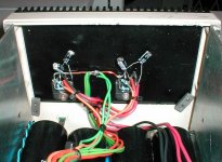
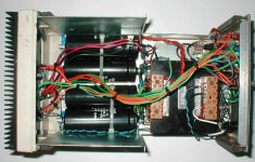
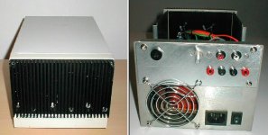
Some pics of the final amp:
Measured DC offset:
Min. Vol: 23.7mV and 18.5mV
Full Vol: 25.7mV and 24.7mV
So at the end of the day, maths and numbers can say what they want, if it sounds good, it IS good 😉 Ain't Hi-Fi about the audio part??
Some pics of the final amp:
Attachments
quote:
JDeV
"So at the end of the day, maths and numbers can say what they want, if it sounds good, it IS good Ain't Hi-Fi about the audio part?? "
You are absolutely correct.
Excellent work by the way!
And I really like your slogan:
"Be carefull who's advice you buy, but be patient with those who supply it free." - Baz Luhrmann
Hi,
Opamp noninv gain is allways Rf/Rin, in this case is 20, and is independent of pot value and slider position.
Overall gain (pot attenuation + opamp gain) for pot 10k midlle position (first example) is about 2.8. My test circuit confirm this calculation (and amp works stable).
Problem with this circuit is too low input resistor. For 10k lin pot the best value for input resistor is about 2-3k and then Rf is about 47k or so. IMHO
Regards
makes sense. and yes the diagrams on the datasheet are all inverted, my bad
for the record, i have little or no electronics knowledge, i just make things and they work

which is funny really, as i do things that are apparentley big no no's. for example, all my parts are quite far from the chip - i built it on stripboard and redirected even numbered pins so they lie on seperate track, this added another inch minimum to parts. i also initialy didn't use bypass caps at all and there were no problems - even at full volume (i've added them since tho just cos i was bored).
many of the things people say you must do i think stem from old wives tales as few people would have actually experimented
goodo
iR
GregGC said:quote:
JDeV
"So at the end of the day, maths and numbers can say what they want, if it sounds good, it IS good Ain't Hi-Fi about the audio part?? "
You are absolutely correct.
Excellent work by the way!
And I really like your slogan:
"Be carefull who's advice you buy, but be patient with those who supply it free." - Baz Luhrmann
i wouldn't call it hi-fi. probably something that sounds good, but not hi-fi as that implies a high fidelity to the original.
theChris said:i wouldn't call it hi-fi. probably something that sounds good, but not hi-fi as that implies a high fidelity to the original.
It's still about the sound - man, the sound 😉 Hi-Fi, Audio, Music, Noise - whatever

- Status
- Not open for further replies.
- Home
- Amplifiers
- Chip Amps
- Min. Inv. LM3886