Hi everyone
one year ago I bought two Aikido 24V and two Max Millet boards, I have assembled them with BJT and MOSFET.
Great DIY project, great sound, really. The "valve sound" when I was young....
I like very much the Aikido sound with the LM317 buffer (great idea!!!!), this is my preferred headphone amply, and I like too the Millet diamond buffer stage, so why don't create a new headphone amp with the best of both Aikido and Millet?
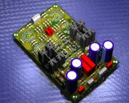
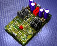
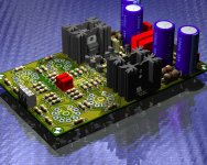
Et voilà here there is the MILLKIDO 24.
The protoype I've designed sounds incredibly well with my HD590 and AKG, with only high quality standard components.
The board is a standard 100x160mm, and I use a single 24 V power line, I've tried an O22 Amb power supply and a 24V switching PS and both works fine.
Like MAX Millet, output transistors can be BJT or MOSFET.
In my personal experience there are too much differences in sound from different LV tubes (6GM8, ECC86, 6H27 ecc) and manufacturers, to
"boutique" the circuit. I love to listen good music on a good ampli with my ears, not the perfection of 20 Hertz square wave or the 0,0001%
distortion, I prefer to change the tubes when I listen jazz or rock or vocal or classic, and believe me, there is difference in tubes models and manufacterers!
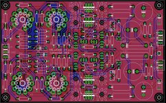
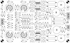
here there are the circuit and the board, so you can play on, enjoy!
one year ago I bought two Aikido 24V and two Max Millet boards, I have assembled them with BJT and MOSFET.
Great DIY project, great sound, really. The "valve sound" when I was young....
I like very much the Aikido sound with the LM317 buffer (great idea!!!!), this is my preferred headphone amply, and I like too the Millet diamond buffer stage, so why don't create a new headphone amp with the best of both Aikido and Millet?
Et voilà here there is the MILLKIDO 24.
The protoype I've designed sounds incredibly well with my HD590 and AKG, with only high quality standard components.
The board is a standard 100x160mm, and I use a single 24 V power line, I've tried an O22 Amb power supply and a 24V switching PS and both works fine.
Like MAX Millet, output transistors can be BJT or MOSFET.
In my personal experience there are too much differences in sound from different LV tubes (6GM8, ECC86, 6H27 ecc) and manufacturers, to
"boutique" the circuit. I love to listen good music on a good ampli with my ears, not the perfection of 20 Hertz square wave or the 0,0001%
distortion, I prefer to change the tubes when I listen jazz or rock or vocal or classic, and believe me, there is difference in tubes models and manufacterers!
here there are the circuit and the board, so you can play on, enjoy!
Attachments
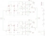
Looks to me like the 0.6V Vbe limit for T1 & T2 would prevent Q3 and Q7 from turning on? Something missing or drawn wrong?
OH, nevermind, I guess the intention is for one OR the other output device.
OH, nevermind, I guess the intention is for one OR the other output device.
Last edited:
- Status
- Not open for further replies.