Hi all
there is a nearly 4Vdc offset in the signal that drives the high side in my H-bridge
and i don't know how to remove it .
i didn't have this problem when i was driving the motor with a high side switch only
i added a RC snubber circuit across the drain and source and every thing was working well i.e no offset ,sharp on/off , no distorion in either the gate or the source signal and the voltage diffrence between the gate and source are nearly above 12 v .
but when i have entered the motor between high and low side switches , a dc offset appears on the gate of the driver of the high side , so the mosfet turn off partially .
and the switching signal across the low side drain is distorted although the gate switching signal of the low side is nearly perfect .
i think it is the miller effect that caused this shift in the high side source and distortion in the low side drain.
but how to compansate miller effect ?
salam
hindi

If you could post a schematic this would help. It's not very clear from your explanation whether you are experiencing a plain DC offset (which can't arise from Cgd effects because it's capacitive) or a gate charge problem. The Cgd can't be compensated for. The art of gate driving is all about finding peaceful living arrangements with it.
Hi all
sorry there is no simulation , because i didn't found the IR2110 driver .
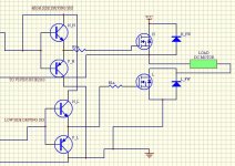
but , here is the schematic
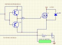
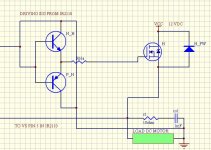
1- Fig 1 ,dc offset in the driving signal and hence in the source signal but when the collector of the PNP transistor is connected to the ground instead of the high side SOURCE, the dc offset had been removed Fig 2.
2- this time the signal had been shifted to nearly 3VDC below the zero Fig3.
3-SCHOTTKY diode added the -VE part of the signal had been removed Fig4 .
4- but the signal at the drain of the low side MOSFET is completly distorted in both the amplitude nearly 5 V and shape although the gate signal is completly good and the Motor was not working .
5- the motor starts to work after adding a RC snubber at the load and the low side , but the drain signal still distorted Fig5 and the high side Mosfet gets hot .
6-when i have tried to add a snubber circuit to both the high and low side Mosfets and the load at the same time the motor doesn't works .
7- so may be the problem is in choosing a suitable RC snubber circuit with an adequit values for the above combination [high Mosfet-LOAD-low Mosfet].
So, how to adjust or tune the snubbers ?
SALAM
hINDI
Attachments
Your circuits show a very strange feature: You are feeding both drivers from the same supply rail.
This would only work in some very restricted cases, i.e. very low voltage feeding the bridge but driver supply voltage higher than bridge supply voltage but still lower than max allowed driver supply voltage.
Feed your upper-side driver with a floating supply voltage !!!!!
Regards
Charles
This would only work in some very restricted cases, i.e. very low voltage feeding the bridge but driver supply voltage higher than bridge supply voltage but still lower than max allowed driver supply voltage.
Feed your upper-side driver with a floating supply voltage !!!!!
Regards
Charles
- Status
- Not open for further replies.
- Home
- Amplifiers
- Class D
- Miller effect in H- bridge


