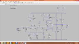
I have the amp in the enclosed spice schematic up and running on a breadboard. It sounds fine.
I also have an ac analysis of the amp in ltspice enclosed. If I understand the plot correctly, this amp should be unstable.
What am I missing? The miller cap was chosen to get a crossover freq of 500khz. As I understand it from Cordell's book (you may notice its his spice models I'm using), the pole at the miller cap should not cause more than 90 degrees of phase lag. Does this mean that there is another pole that is in play here? Like I said, I have this amp up and running with no obvious problems.
The only discrepancy between the spice sim and the built amp is the output transistors. The actual build has mje 2955/3055. I don't have models at hand for those. I don't see that this would be a factor though.
Is the sim correct, and I don't know how to interpret the data? Is the sim correct and my amp is unstable and it hasn't been audible/noticeable yet? Is there a problem with my sim?
Any ideas?
Attachments
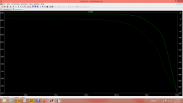
Why? It looks OK to me. It would be easier to figure out the stability margins if you did an AC analysis on either the loop gain or the open loop gain, instead of the closed loop gain.If I understand the plot correctly, this amp should be unstable.
I calculate ULGF = 1 / (2 * pi * 30pF * 295 Ohms) * 1 / 23 = about 850KHzThe miller cap was chosen to get a crossover freq of 500khz.
There's always extra unwanted poles. That's why we need compensation in the first place.Does this mean that there is another pole that is in play here?
I also have an ac analysis of the amp in ltspice enclosed. If I understand the plot correctly, this amp should be unstable.
...
Is the sim correct, and I don't know how to interpret the data?
What you have plotted is the response of the amp, from input to output.
To check stability you need to plot the gain around the feedback loop.
They are quite different but are often referred to with names that sound similar, as above.
Best wishes
David
Last edited:
@godfrey. I thought I needed to add both degeneration resistors and both re's for the crossover freq calc.
also, I don't understand the 1/23 part either.
also, I don't understand the 1/23 part either.
No, because you're using a current mirror between the input stage and second stage. What you said is correct for amps that have a single resistor instead of a current mirror, as they only use the output from one half of the input stage.@godfrey. I thought I needed to add both degeneration resistors and both re's for the crossover freq calc.
The closed loop gain is 23, set by R9 and R10. So the unity loop gain frequency is the frequency at which the open loop gain falls to 23.also, I don't understand the 1/23 part either.
ok, I realized what the 1/23 part was about after I posted. The current mirror effect on the calculation never occurred to me. It makes sense that it would have some effect, but I am having trouble sorting it in my head. Actually, to me it seems like it should be opposite (use both for the mirror, just half the resistance for the single resistor load)
Obviously I am not getting something
Obviously I am not getting something
Remember, gain of the input stage is proportional to 1 / emitter resistance. Using the mirror gives double the output, as would halving the emitter resistance.
ok, that brings up another question. Does this mean I need to use the full 2.5mA that the LTPs current source provides in my slew rat calcs? Right now I have been using just half. I feel like that should still be the case though, right?
The sim won't show any problem, but when you come to building the real amplifier you must reduce C2 by a factor of at least 20. Try 2u7F or 3u3F, or maybe even 2u2F.
Add an Output Zobel, or preferably a Thiele Network.
Add an Input RF filter.
Add an Output Zobel, or preferably a Thiele Network.
Add an Input RF filter.
Yes, max slew rate = 2.5mA / 30pF = about 80V/uSok, that brings up another question. Does this mean I need to use the full 2.5mA that the LTPs current source provides in my slew rat calcs?
- Status
- Not open for further replies.
- Home
- Amplifiers
- Solid State
- miller comp question