Ok,
Since I figured out that the Miller C of a triode strapped pentode/beam power tube is a difficult thing to nail down I have made a conservative guess at the miller of my paralleled triode strapped 829B.
Now, here is another question and please excuse me if it seems I am a bit "dense", I have had all this stuff swimming in my head and I am a bit "lost".
Assuming I am driving the paralleled grids with an RC amplifier. (6CG7/6FQ7)
When calculating the response of the output (829B) I use the Miller Capacitance and the Output Impedance of the driving stage + "grid stopper" resistance?
This "pole" is the low pass correct?
The Grid to ground resistor and the Miller is another pole high pass?
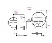
I have attached a section of the design I am working on with some approximated values. Can anyone help with the F3's??
Since I figured out that the Miller C of a triode strapped pentode/beam power tube is a difficult thing to nail down I have made a conservative guess at the miller of my paralleled triode strapped 829B.
Now, here is another question and please excuse me if it seems I am a bit "dense", I have had all this stuff swimming in my head and I am a bit "lost".
Assuming I am driving the paralleled grids with an RC amplifier. (6CG7/6FQ7)
When calculating the response of the output (829B) I use the Miller Capacitance and the Output Impedance of the driving stage + "grid stopper" resistance?
This "pole" is the low pass correct?
The Grid to ground resistor and the Miller is another pole high pass?
I have attached a section of the design I am working on with some approximated values. Can anyone help with the F3's??
Attachments
~15 KHz
I am assuming -3db at 15K based upon what?
25K + 1K5? and the 250 pf?
I guess what is confusing me is this:
The Zout of the driver is about 25K, the grid stoppers are in series with that, correct?
the pole then becomes an LP -6db/octave with Fc = 1/ (2 X PI X 26,500 * (250pf)
So the -3db point is about 25Khz so flat up to 12,500hz?
So for this calc the grid to ground resistor is ignored?
The coupling cap and the grid resistor are then a high pass filter correct?
Miller Cap only affect high frequency response?
Please someone help confirm all this and I can then "get my head on straight"
The Zout is in parallel with 100K grid leak resistor. Add a grid stopper and you get 21.5K. Xc=1/2PiFC.
250pF and 20K give about 30 KHz pole (you may use a calculator to get it precise, but as soon as 250 pF is your educated guess you may roughly calculate in mind), that mean -3dB frequency is an octave below, i.e. about 15 KHz.
Miller capacitance not only affects high frequency response; it adds as well phase intermodulation distortions.
Perfect, NOW I understand the grid leak is parallel to the Zout.
If I am using the (2) sections in parallel and (2) grid stoppers should I be calculating 1/2 of the capacitance?
eg; Looking IN to the grids I have essentially two paths to the grids of each section. They have the same resistance so 1/2 goes to each correct?
If so, then shouldn't I calculate based upon Zout [] Grid leak + (1) Grid stopper and the Miller C of 1 section?
Actually, you should assume grid stoppers in parallel.
I.e. instead of 21.5K you have 20.75K
And a total Miller (i.e. the sum of them) you are driving with 20.75k resistance. So, if 250 pF is Miller capacitance of one half you have 500 pF total.
I.e. instead of 21.5K you have 20.75K
And a total Miller (i.e. the sum of them) you are driving with 20.75k resistance. So, if 250 pF is Miller capacitance of one half you have 500 pF total.
Wave,
You are awesome!
One of the major issues I had a while back was that I tended to get ahead of myself. I was trying to "design" before I even understood what I was "designing" (actually just ripping off bits and pieces of other schematics.
So, someone on here suggested I do a little reading and learn the basic math and theory behind all of this. Well, I guess I went a little to far in the reading and "learning" dept. and got myself all crossed up.
So..this is another "AHAA" moment! To be honest most of the texts available about vacuum tubes are rather dry and verbose as well as OLD! Most of the "newer" texts are about "new" approaches and sometimes complex approaches to designs.
I know I should just use a follower and forget about the high miller fo the 829B. But for that matter I should just forget the 829B right? Too me the 829B is like an "Everest" thing, I will build it because it is there.
I have just started forming my own opinions on design approaches and my first rule is I want to avoid any stages that are not absolutely neccessary. To me a cathode follower is to be avoided if possible. (less than unity gain and added distortion etc only to get low Zout)
If I can use a more traditional grounded cathode amp stage (albeit with low gain) and get a relatively low Zout I might be happy.
Thank you again for the insight and clarification. I am going to start a thread on this amp idea and detail my progress.
I suggest you to read some recent topics about parallel feedback by voltage, when an output pentode is connected like an inverting opamp.
Advantages?
You are getting triode-like results, but under your control. Low Miller capacitance; choosing feedback ratio you are controlling output resistance; supplying a screen grid by low and regulated voltage you are getting good linearity; you carefully limit power dissipated by the 2'nd grid, while can go with anode voltage as high as it can take without worrying about a fragile and covered by anode screen grid that can't radiate heat.
But when a screen grid is tied to anode you are limited by only one set of curves; you are getting big Miller capacitance; and you are limited by screen grid's power dissipation, when anode still can dissipate more!
"Triode strapping" is no more than an exercise for those who wants to "experience triode sound" cheap without real powerful triodes.
I understand exactly what you are saying. I have also read about placing a simple Diode in the screen grid circuit to essentially allow the screen to do the job it would have in a Pentode circuit but using overall "triode" topology.
If I used a regulated supply to the screen grids and went with a Pentode topology I could get "ridiculous" power out of it. The limiting factor then becomes the budget for OPT's Power Tranny etc, rather than the Screen Grid voltage. Since I have heard of good performance and tube life with the G2 voltage as high as 350V in a "Triode Strapped" 829B I am building around a B+ of about 300V.
My budget is virtually non-existant at this point (out of work) so I am limited to the power tranny and OPT's I have. This initial go around will be aimed at getting about 15W with 1 - 2% distortion.
In the future I would pull the stereo amp apart and go with mono blocks having their own power supplies and screen supplies, fixed bias etc. Sky's the limit in the future.
This first "budget" build will be the starting point of what could be a real interesting progression.

- Status
- Not open for further replies.
- Home
- Amplifiers
- Tubes / Valves
- Miller Capacitance AGAIN!