Attached is a schematic of the second of a series of compact single-ended tube amplifiers with switching power supplies. This amp uses a pair of 6LR8 triode/pentode vertical deflection tubes (with pentodes triode strapped) for what should be somewhere between 3-4 W output, The circuit shown uses the triode tube as the input amp with a current source load consisting of a DN2540N5 depletion mode MOSFET. The power pentode is triode strapped and cathode biased using an amplified zener voltage source (components R12,13,15-17,19,22, Q11,13,14, U1, C2,3,6). This voltage source is proposed as an alternative to the LED array used by SY in his "Red Light District " push -pull amplifier. The voltage source receives additional bias from the plate supply through resistors R11 and R25 so that it is never cut off, even if the output tube is cut off. Additional bias is provided for voltage reference U1 through resistor R24 to swamp out voltage variations due to curent variation in Q14.
This circuit was brought up on the bench this afternoon using external DC sources for the filament and HV supplies, and bias in the output stage was adjusted to ~45mA. Bias is stable, and no magic smoke was released. The next step is to finish mounting the input and output jacks on the rear panel and mating the amp with its switching power supply, which is already thouroughly wrung out.
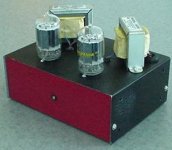
Pictures will follow when the amp is assembled and the chassis is painted its final colors (Top/sides, black crackle, front and back, red crackle with yellow LED indicator).
This circuit was brought up on the bench this afternoon using external DC sources for the filament and HV supplies, and bias in the output stage was adjusted to ~45mA. Bias is stable, and no magic smoke was released. The next step is to finish mounting the input and output jacks on the rear panel and mating the amp with its switching power supply, which is already thouroughly wrung out.
Pictures will follow when the amp is assembled and the chassis is painted its final colors (Top/sides, black crackle, front and back, red crackle with yellow LED indicator).
Attachments
Hi,
Interesting little amp. Vertical tubes put to great use 🙂
With R11 and R25 holding the output at Va-k/2, why not just lose them and DC couple to the driver?
Cheers!
Interesting little amp. Vertical tubes put to great use 🙂
With R11 and R25 holding the output at Va-k/2, why not just lose them and DC couple to the driver?
Cheers!
R11 and 25 are to keep bias current going through the cathode shunt regulator under all conditions. The cathode is biased at ~45V, set via experiment on the bench, as I was too lazy to plot a series of triode-connected curves for the 6LR8 pentode section. The plate of the input triode is at ~160V, with bias set at ~2mA by Q10.. DC coupling would not be a good idea..
Hi,
OK, gotcha.
As a side note, have you noticed a "sweet spot" too with vertical deflection tube high gain triode sections @ 2mA with 160-200V on the anodes? I did a comparison of sound between several and found that to be a common trait among the ones I tested 😕
Cheers!
wrenchone said:The cathode is biased at ~45V....The plate of the input triode is at ~160V..
OK, gotcha.
As a side note, have you noticed a "sweet spot" too with vertical deflection tube high gain triode sections @ 2mA with 160-200V on the anodes? I did a comparison of sound between several and found that to be a common trait among the ones I tested 😕
Cheers!
The rationale I used was to set the plate voltage on the input triode to about 1/2 the B+ voltage for max symmetric swing. I also wanted some decent current through the input triode so it wouldn't be like some starved, puking 12AX7. At ~160V Vp, this is ~2 mA.. If this turns out to be a sweet spot, all the better...
This little guy is up and running and was playing softly into a pair of so-so Infinity mini-towers at work this evening. I'll be taking it to Burning Amp this weekend, hoping to pair it with some tweeters or a pair of very efficient speakers, as we're talking 2-3W/channel. Actually, now that I've freed up a pair of Edcor XSE-15-8-5k transformers, I could turn this into an ultralinear amp and eke out a watt or two more, but not until after this weekend.
Edcor XSE-15-8-5k transformers, I could turn this into an ultralinear amp and eke out a watt or two more, but not until after this weekend.
I built a "spud" amp using the 6LR8. I was after the minimum number of parts approach. it can be found here:
http://www.diyaudio.com/forums/showthread.php?s=&threadid=125963&highlight=
The 6LR8 does like UL and 5 watts is easy to get. At least in my circuit plate to plate feedback (resistor from driver plate to output plate) works wonders and no GNFB is needed. The little amp sounds much bigger than its size. I am using the same Edcors and an Antek power toroid from Ebay. Of course I had to explore the limits of the 6LR8. They can take a lot more than the published ratings.
I'll be taking it to Burning Amp this weekend
Too bad that you guys are on the other side of the country, otherwize I would be there.
Too bad that you guys are on the other side of the country, otherwize I would be there. [/B]
Burning Amp, the Vancouver Island DIY Fest, VSAC (my home town, BTW)...
Is there nothing similar for those of us washed up on the Gulf Coast?
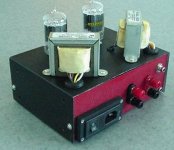
Here's a rear view of the amp. Today I auditioned it with a pair of Paradigm towers that live in the audio testing room at work. The Paradigms are much more sensitive than the Infinity speakers I was using last night, so this little amp really kicked butt. I'll be very pleased and proud to present it at BA - it may open a few eyes.
Attachments
Just as a statement of purpose, the aim of this amp was to test an alternate approach to biasing the final stage. The standard approach of cathode biasing using a resistor shunted by a large cap would have been a minimum parts solution, and would've worked ok. The purpose here was to present a biasing scheme that would be less compromised during large transient excursions. Another approach would have been to use an LED array like SY did in his "Red Light District" amp, but I didn't want all the gaudy lights and we'd sort of tossed the gauntlet down in a friendly fashion at the last Burning Amp when I mentioned this particular idea. So, here it is - an amp biased with a fast semiconductor-based voltage source. I look forward to some listening tests with sensitive, well-articulated speakers. There was certainly some "slam" using the Paradigms.
Hi Wrenchone
Looks like a nice project, and I hope it sounds very good, to motivate me to put the 21LR8's I received yesterday to good use.
I am curious about your subjective evaluation of the biasing block. I have to admit that I do not yet understand how it works, but if evaluation of the amp is positive at the festival I will spend some time trying to get a grasp on it.
Erik
Erik, if I were you I would go ahead and build a 21LR8 amp with whatever circuit makes you comfortable. The FET loaded front end with a passive cathode biased UL output would sound quite nice and be very simple. With the proper construction, other output bias schemes could be built on perf board and retrofitted as desired. After all, the amp you have will sound much better than the perfect paragon you haven't gotten around to building just yet...
"Mighty Mite" saw its day in the sun (there was actually some in the afternoon) at BA. The only fly in the ointment was that few people had speakers quite efficient enough for a flyweight amp like this one. I'll runs some plots of the voltage across the bias circuit during square wave excitation (just for SY - and for my curiosity), but I think the concept has proved its worth sufficiently to try it with a higher powered amp.
- Status
- Not open for further replies.
- Home
- Amplifiers
- Tubes / Valves
- "Mighty Mite" Single Ended Amplifier