What is the expansion profile of the K402? Has anyone found any drawings?
I have already posted Roy's design notes here so doing one from scratch would be a no-brainer given:
Mouth Overall 39-7/16" x 25-1/2" (including flanges)
Horizontal Flange Width: 2-1/4"
Vertical Flange Width: 2-1/2"
Length 16-1/4"
For a 3-Way Jubilee, I would use the BMS 4599nd (see attachment)
and redesign the neck transition to match this driver using salami-slice construction. Otherwise the body build from plywood panels, kerfed on the backsides, for bending, and appropriately strutted and cleated, should not be an overwhelming challenge. WHG
Attachments
Otherwise the body build from plywood panels, kerfed on the backsides, for bending, and appropriately strutted and cleated, should not be an overwhelming challenge. WHG
Your construction skills are probably ahead of mine.
Because the throat is the most fiddly part, the approach I currently fancy is to start with a horn that's pretty good, and extend the mouth, where precision is not as vital (as previously discussed; posts 22-23 in the link show some cheap horn options).
http://www.diyaudio.com/forums/multi-way/300870-how-choose-horn-waveguide-home-audio-3.html
Last edited:
Those look to be about the same size as my EV CE 9040 horns.
You mean the HR9040?
Caveat Emptor
I find that most commercial horn offerings have not been tailored to the exit profile of any specific driver. A neck (adapter), once designed to match the driver to the horn body, can be sent to a CNC shop for finish machining of the internal profile. If you can do the tool paths, that should save you some money. Send three blanks. The first is for calibration. WHG
Your construction skills are probably ahead of mine.
Because the throat is the most fiddly part, the approach I currently fancy is to start with a horn that's pretty good, and extend the mouth, where precision is not as vital (as previously discussed; posts 22-23 in the link show some cheap horn options).
http://www.diyaudio.com/forums/multi-way/300870-how-choose-horn-waveguide-home-audio-3.html
I find that most commercial horn offerings have not been tailored to the exit profile of any specific driver. A neck (adapter), once designed to match the driver to the horn body, can be sent to a CNC shop for finish machining of the internal profile. If you can do the tool paths, that should save you some money. Send three blanks. The first is for calibration. WHG
The short answer is conical, but with the accoutrements of a typical waveguide added. However, it has been described by the creator as being an adaptation of tractrix. At the end of the day it's anyones call IMO.What is the expansion profile of the K402? Has anyone found any drawings?
The only non-permanent ways I can think of is to build one into a wardrobe ...or if aesthetics are unimportant, mount one in a window, like an airconditioner.
You can simply vent them outdoors, like this chap's infinite baffle sub:
William Cowan's Homepage
A few years ago, I pointed a friend (who was renovating) at the IB concept. He looked at some on-line info, and installed his subwoofer in the crawl space under his house. The bass vented into the room via an iron grill in the floor.
If I recall correctly, he used a ply box as the manifold, and a section of sonotube as the rear chamber for each driver ...so not a true (huge) IB, but still a very cheap and easy way to have a large bass enclosure without using up any in-room space.
Agreed. With a little creativity, many installation possibilities will arise. As good as they are, you will notice they are not very popular. I learned about them in the middle 1970's when I first started studying speaker-building.
For my tastes, they are an optimal performer. For my install, I jutted out a room corner which backed up to a 500 cubic foot closet. My I.B. install actually creates an additional wall, which is 45 degrees to the listening room.
I do believe this has created a very nice environment for bass. All listeners who visit me, tend to agree. My system is featured in Copper magazine isuee #29. It's obviously very much a DIY and unfinished system as far as aesthetics go; I don't have a problem with WAF, but I do have some superb sound quality 🙂
What is the expansion profile of the K402? Has anyone found any drawings?
https://community.klipsch.com/index.php?/topic/156859-k-402-in-wood/
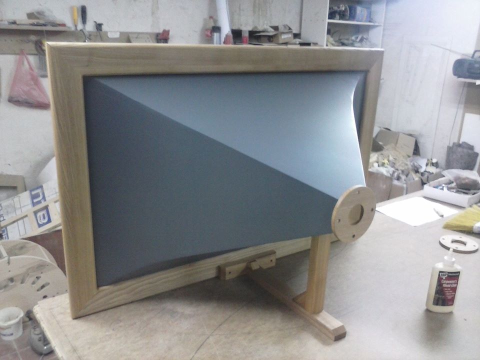
From what i can gather, it is conical, with a tractrix expansion at the mouth. It is almost as if they plotted a tractrix curve and stopped when the angle was the same as the desired conical angle.
I have looked at tractrix equations, but I don't understand how to calculate a curve for a given loading frequency, otherwise i'd have a go at writing a program that can do this
I have looked at tractrix equations, but I don't understand how to calculate a curve for a given loading frequency, otherwise i'd have a go at writing a program that can do this
Borderline Case
Plane Wave assumptions needed to make bass horn design tractable, do not work well for horns designed to operate at higher frequencies. The higher the frequency, the greater the error. The area expansion needed is over some curvilinear wave-front surface that is not easy to determine, quantify, and is much different than the underlying plain surface. For horns that open up quickly three facts are known:
1) the attenuation slopes are so gradual, that the notion of a cut-off frequency has little utility.
2) to get to a length > 1/4 wavelength of lowest frequency to be passed (Usually and octave below the c/o frequency) yields a large horn mouth.
3) because the mouth is so big, reflectance is very low.
That is why Roy's horn in so big and sounds so good.
The only place where I believe there is room for improvement is in the throat design where the wave front exiting the driver needs to be gradually transformed to match the boundary conditions of the horn. While the present discontinuity between driver exit and horn entry is small, it is occurring in an acoustic high pressure zone, so the attendant diffraction is unnecessarily severe. WHG
From what i can gather, it is conical, with a tractrix expansion at the mouth. It is almost as if they plotted a tractrix curve and stopped when the angle was the same as the desired conical angle.
I have looked at tractrix equations, but I don't understand how to calculate a curve for a given loading frequency, otherwise i'd have a go at writing a program that can do this
Plane Wave assumptions needed to make bass horn design tractable, do not work well for horns designed to operate at higher frequencies. The higher the frequency, the greater the error. The area expansion needed is over some curvilinear wave-front surface that is not easy to determine, quantify, and is much different than the underlying plain surface. For horns that open up quickly three facts are known:
1) the attenuation slopes are so gradual, that the notion of a cut-off frequency has little utility.
2) to get to a length > 1/4 wavelength of lowest frequency to be passed (Usually and octave below the c/o frequency) yields a large horn mouth.
3) because the mouth is so big, reflectance is very low.
That is why Roy's horn in so big and sounds so good.
The only place where I believe there is room for improvement is in the throat design where the wave front exiting the driver needs to be gradually transformed to match the boundary conditions of the horn. While the present discontinuity between driver exit and horn entry is small, it is occurring in an acoustic high pressure zone, so the attendant diffraction is unnecessarily severe. WHG
Last edited:
The only place where I believe there is room for improvement is in the throat design where the wave front exiting the driver needs to be gradually transformed to match the boundary conditions of the horn. While the present discontinuity between driver exit and horn entry is small, it is occurring in an acoustic high pressure zone, so the attendant diffraction is unnecessarily severe. WHG
I get the feeling that this is deliberate and that drivers with large throat angles will work best in the K402
Here are some internal images of the MK 2 version of the K-69 showing its wider throat angle
A low exit angle driver can be adapted to a wide horn using the OS profile, with a minimal diffraction penalty.
This also depends on the wavefront curvature conforming to the driver exit angle as, for example, a plane wave front emanating through a conical orifice with positive expansion would be an erroneous condition.
At midrange frequencies an OS adaptation should be simple and innocuous.
This also depends on the wavefront curvature conforming to the driver exit angle as, for example, a plane wave front emanating through a conical orifice with positive expansion would be an erroneous condition.
At midrange frequencies an OS adaptation should be simple and innocuous.
A low exit angle driver can be adapted to a wide horn using the OS profile, with a minimal diffraction penalty.
This also depends on the wavefront curvature conforming to the driver exit angle as, for example, a plane wave front emanating through a conical orifice with positive expansion would be an erroneous condition.
At midrange frequencies an OS adaptation should be simple and innocuous.
How should one define the throat entry angle in a midrange horn driven by a cone?
Phase Plug
design you use will be the determinant, and at best it will be a SWAG as to the wave front profile coming out of it. Recommend you treat the PP and neck transition (round to rectangular if needed) as an adapter between the driver and the horn. That way if you decide to change the driver later you don't have to modify the horn body. The bounding condition should approximate a segment of a hyperbola, declining in curvature away from the PP such as used in a OS horn. WHG
design you use will be the determinant, and at best it will be a SWAG as to the wave front profile coming out of it. Recommend you treat the PP and neck transition (round to rectangular if needed) as an adapter between the driver and the horn. That way if you decide to change the driver later you don't have to modify the horn body. The bounding condition should approximate a segment of a hyperbola, declining in curvature away from the PP such as used in a OS horn. WHG
Yes ....
.... but not for the reasons you suppose. WHG
I get the feeling that this is deliberate and that drivers with large throat angles will work best in the K402
Here are some internal images of the MK 2 version of the K-69 showing its wider throat angle
.... but not for the reasons you suppose. WHG
Yes,
by design, and that is why it is of superior performer. The underlying analytical geometry is a tool to be used, not a master to be served. There is no safety-net when it comes to an HF acoustic horn design. WHG
It's a really shallow horn , too shallow to be tractrix. All mouth
by design, and that is why it is of superior performer. The underlying analytical geometry is a tool to be used, not a master to be served. There is no safety-net when it comes to an HF acoustic horn design. WHG
A phase plug isn't always used with a cone/mid arrangement, although one could be used to define any exit angle needed, in theory but there are often constraints in a design. Said angle would be, for example, the relative angle of radii bounding a spherical cap.How should one define the throat entry angle in a midrange horn driven by a cone?
It is often enough to be able to bring the wavefront to plane, and this is probably a good default to achieve between a cone and the start of the horn proper. Without a phase plug, quarter wavelength (at Fh) tolerances might be used to justify reduced accuracy.
Depends
When wavelength of the highest frequency to be passed is much larger than throat and driver dimensions then the issues addressed by a phase plug do not matter. The only issues that remain are air flow resistance/turbulence and front cavity air mass. Otherwise, sans phase plug functionality, you are giving up band-width, efficiency, driver/cavity mode mitigation, and the ability to establish a coherent wave entering the horn, all for sake of manufacturing convince. WHG
A phase plug isn't always used with a cone/mid arrangement, although one could be used to define any exit angle needed, in theory but there are often constraints in a design. Said angle would be, for example, the relative angle of radii bounding a spherical cap.
It is often enough to be able to bring the wavefront to plane, and this is probably a good default to achieve between a cone and the start of the horn proper. Without a phase plug, quarter wavelength (at Fh) tolerances might be used to justify reduced accuracy.
When wavelength of the highest frequency to be passed is much larger than throat and driver dimensions then the issues addressed by a phase plug do not matter. The only issues that remain are air flow resistance/turbulence and front cavity air mass. Otherwise, sans phase plug functionality, you are giving up band-width, efficiency, driver/cavity mode mitigation, and the ability to establish a coherent wave entering the horn, all for sake of manufacturing convince. WHG
- Status
- Not open for further replies.
- Home
- Loudspeakers
- Multi-Way
- Midbass horn: how to solve the range below it?