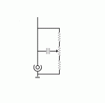
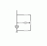
Still can't figure it out, as I cannot identify how and where the conncetions go to the parts not drawn -- pickup, volume pot (usually behind a tone circuit, your tone circuits go straight into the output jack with either no vol pot at all or in front of it?) Why not use standard conventions like signal flow from left to right, series elements horizontal, parallel elements vertical, a horizontal GND buss, signal above it, etc?
Anyway, this is quite off-topic here...
Anyway, this is quite off-topic here...
- Status
- Not open for further replies.


