It's possible to use microwave transformers to tube amps? Of course that is needed rewinding the secondary, unless that I try to make a amp that need 2.5kV.
I already read about someone that used microwave transformers to obtain 12V at high currents, like 60, 50A... But my question is for tube amps...
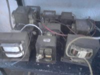
I have a few MOTs here, and thats why I'm asking.
Thank you.
I already read about someone that used microwave transformers to obtain 12V at high currents, like 60, 50A... But my question is for tube amps...
I have a few MOTs here, and thats why I'm asking.
Thank you.
Attachments
It's possible to use microwave transformers to tube amps?
Sure, it's possible, but probably overkill, but if you have some, and the primaries aren't fried, you could do it. If you're certain of the primary, connect it (beware of that HV seconary!) and see how much voltage the heater winding for the magnetron gives you. Then see how many turns it has to get your volts/turn ratio.
Once you know that, and your design nominal voltage(s) you can replace the HV secondary with whatever secondary(ies) voltages you require. The "traditional" wire sizing is 700cm (circular mils) per amp for most PTX's. You might go 1000cm/A just to be on the safe side, and run a bit cooler.
I got a some of these MOTs as well. Some for HV experiments, some for u-wave experimentation, and some fried ones that I might recover the iron from to make high current choked for a parafeed MOSFET SS design some day.
What you need to look out for are the MOTs that include a "magnetic shunt", that has to go, or you need a different MOT. These mag-shunts ruin voltage regulation.
Many MOTs have a very low turns/volt and draw a lot of idle current. They are not designed to be run for long periods of time (hours).
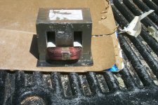
You'll find there's two soft iron slugs, that form the magnetic shunt.
I beat them out with a punch! You can make some useful transformers with these after that. They will happily run for hours after these are removed.
I beat them out with a punch! You can make some useful transformers with these after that. They will happily run for hours after these are removed.
I have punched out the shunts - not easy but possible. I used mine as plate chokes and power supply chokes. Not really enough inductance for plate choke duty though.
Shoog
Shoog
Soft iron shunts ?
Where is the soft iron shunt usually ? between the 2 windings of wire ?
Thanks.
Srinath.
You'll find there's two soft iron slugs, that form the magnetic shunt.
I beat them out with a punch! You can make some useful transformers with these after that. They will happily run for hours after these are removed.
Where is the soft iron shunt usually ? between the 2 windings of wire ?
Thanks.
Srinath.
I've also seen a couple of MOT's that had a weld that effectively shorted all the laminations together. Will depend a lot on what you are trying to achieve with them, but I'd expect them to not be particularly quiet in use
Welded laminations is a quick and convenient method of manufacture - it may look bad, but the weld is just a very small fraction of core area that it doesn't usually matter for power applications. It is certainly practical for making very large choke cores (eg. UI style) where the UI gap outer edge is welded (the weld saturates very quickly to become like air).
OK These have a line of weld on the outer wall in 4 places. It wont matter ?
Now what is noise ? I thought noise in a power supply is a bunch of ac in dc supply mainly due to cheapo manufacturers under capping. I thought I can get clean DC with a big filter cap ...
Cool.
Srinath.
Now what is noise ? I thought noise in a power supply is a bunch of ac in dc supply mainly due to cheapo manufacturers under capping. I thought I can get clean DC with a big filter cap ...
Cool.
Srinath.
The welds won't matter - a cheaper way to manufacture en masse, as no need to punch holes in laminations and use bolts/nuts, or to make up a separate clamping cover which adds cost.
Your noise comment is not quite right, but the topic gets quite complex for hi-fi/esoteric designs. Best to search around a bit for tutorials on ripple voltage and rectifier noise for a much better understanding. For guitar use that recreates the sound of old amps, then power supply ripple is often observed as a subtle but good 'input' in to the tone of the amplifier.
Your noise comment is not quite right, but the topic gets quite complex for hi-fi/esoteric designs. Best to search around a bit for tutorials on ripple voltage and rectifier noise for a much better understanding. For guitar use that recreates the sound of old amps, then power supply ripple is often observed as a subtle but good 'input' in to the tone of the amplifier.
I managed to nick the 110v side in one of the transformers.
Is there a way to repair it. Its not cut through, its basically nicked.
Cool.
Srinath.
Is there a way to repair it. Its not cut through, its basically nicked.
Cool.
Srinath.
I see these are all isolated bobbins.....Couldn't one just start un-winding the secondary say Ten winds, Power up & measure....at say ten turns per, Just keep on going till your AC is where you want it a bit higher than you want it loaded, a simple wirewound............sure on will be puling varnish with it as you in-wind but wouldn't that be best?
_______________________________________________Rick.........
_______________________________________________Rick.........
The secondary is wound so freaking tight in there - even if you got rid of all the lacquer, ther is no room. The secondary is the limiting factor. I think it had something like 20,000 windings of 30-33 gauge wire. You will never get 1 turn out ... you cant. The best way it to cut off the exposed parts. Then sink a drill through the part between the EI core and after you get 3-4 holes per side, you can knock it away from the wall and knock it out. That secondary was machine wound outside and then stuffed with the core laminations.
Now the primary - there is a ton of room. Loosen the lacquer and it will come apart turn by turn. Anyway my nicked primary, I am not risking the thing blowing. Its been cut out and removed just in case in a round of idiocy I decide to use it.
Cool.
Srinath.
Now the primary - there is a ton of room. Loosen the lacquer and it will come apart turn by turn. Anyway my nicked primary, I am not risking the thing blowing. Its been cut out and removed just in case in a round of idiocy I decide to use it.
Cool.
Srinath.
Mind you that isolation is also made cheap on microwave oven transformers, hence why one end of the secondary is grounded to the core.
The primary winding is close to 1V/turn and in order for it to run for hours without heating it is a good idea to add additional primary windings.
As someone else also stated, MOTs were constructed for run times less than 15 min at full power, are placed in a well ventilated enclosure and there is also a fan near it (mainly for the microwave head though). It is from birth running on the edge of total saturation and is why measures have to be taken in regard to primary coil.
I have run my microwave for over 90 min - not continously, but back to back. A big bowl of rice = 22 min cook time, we do that very very often. Bigger bowl for say an extra guest = 30 min. I've done 3-4 of those back to back like having a party. In the humid and hot environment it lives in I think its designed very very well for life in audio. Its water and humidity that kills em. Atleast that's what they say when a transformer explodes in India.
But I will add a 5v fan to cool it.
I have a few questions.
What exactly does that shunt do - to me it looked like it will siphon off some of the magnetism running through the middle of the EI core. Removing it will get me closer to 1v per turn ? Its already removed and going to be replaced with cardboard or plywood.
Cool.
Srinath.
So let me get this straight, if I punch out these "extra" laminations it will free things up so I can 'spin' the secondary so I can pull off some turns?
I'll get these out first & see what I've got.
_____________________________________________________Rick........
I'll get these out first & see what I've got.
_____________________________________________________Rick........
The secondary modification is IMHO a red herring.
If you were able to knock out the shunt laminations - that is a big if - you damage the primary and it is worthless ... anyway if you get the shunts out. and you can gently unwind the secondary - you would still be left with a 1/2 amp max ... capacity wire with a step up of about 20X.
The transformer takes 110v @ 10 amp and send out 2000 v @ 1/2 amp. In a 1000 watt microwave.
Chopping off the secondary is your best bet. Especially if your target is a 50-80v dc supply. Its easy to hand wind a 10-12 awg wire 35-50 turns on the secondary.
If you want to turn say 300-500 turns and get a bigger output voltage. I would think you would be better off cutting the transformer open into the E's and I's. You'd measure it before cutting it open, then you use a winding technique like making or getting a bobbin and winding it. Then putting it back together.
Cool.
Srinath.
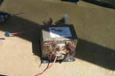
Pics attached.
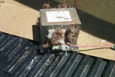
These are pics I got off the ones I gutted.
That secondary is a royal mess - I did better on the first one than the second but that was due to the way it was wound.
Cool.
Srinath.
These are pics I got off the ones I gutted.
That secondary is a royal mess - I did better on the first one than the second but that was due to the way it was wound.
Cool.
Srinath.
Attachments

Last edited:
- Status
- Not open for further replies.
- Home
- Amplifiers
- Tubes / Valves
- Microwave transformers