this is for peltor comtac III's and TCI TABCIII radio ptt headsets. the mic ohms out at 150.
i have made this circuit
Dynamic to electret mic
i get horrible motorboating noise (digital only, analog fine)
at first i thought it could be the cheap kenwood k1 cable i harvested off a baofeng ptt
even just with ptt connected, no headset/mic it still does it. only thing it can be now is the pre amp im using to make the mic work, any suggestions or better circuits to try?
Motorboating is typically breakdown of a capacitor. This circuit is so simple there are only 4 capacitors. The input .022 uf capacitor. The power bypass capacitor at the output of the power supply, typically a 10 uf or higher. The capacitor of the input cable. The capacitor of the output cable. If you have made a bad solder joint, sometimes those act as capacitors. A bad solder joint may sometimes pass higher voltage, and block lower voltages.
Use a VOM on 20 vdc scale to look that the dc voltages happening at the input, power supply rail, and output, to get some idea where the voltage variation occurs. DVM are too slow, typically. The dual slop integrator averages over 2 to 4 seconds. I've had analog VOM so fast the pointer would vibrate nearly full scale at 60 hz if I plugged it in the wall on 250 vdc. So a VOM should be fast enough to show where the motorboating originates. Oscilloscopes are good but maintenance of a scope is very expensive, and there are those $50 probes that are trash if you step on it. Meter leads are $6 the pair if you step on one or get it tangled with the soldering iron.
Good luck.
Last edited:
Motorboating is typically breakdown of a capacitor. This circuit is so simple there are only 4 capacitors. The input .022 uf capacitor. The power bypass capacitor at the output of the power supply, typically a 10 uf or higher. The capacitor of the input cable. The capacitor of the output cable. If you have made a bad solder joint, sometimes those act as capacitors. A bad solder joint may sometimes pass higher voltage, and block lower voltages.
Use a VOM on 20 vdc scale to look that the dc voltages happening at the input, power supply rail, and output, to get some idea where the voltage variation occurs. DVM are too slow, typically. The dual slop integrator averages over 2 to 4 seconds. I've had analog VOM so fast the pointer would vibrate nearly full scale at 60 hz if I plugged it in the wall on 250 vdc. So a VOM should be fast enough to show where the motorboating originates. Oscilloscopes are good but maintenance of a scope is very expensive, and there are those $50 probes that are trash if you step on it. Meter leads are $6 the pair if you step on one or get it tangled with the soldering iron.
Good luck.
i dont really understand, the schematic i posted only has one cap? im very experienced at soldering qfp chips and any smd
Read a cable supplier catalog to determine the capacitance per meter of cable, also the ultimate breakdown voltage.
Read a power supply manual about the necessity of capacitors on the output of DC power rectified from AC power from either a mains transformer, or a switcher supply oscillator transformer. If your circuit uses batteries, it doesn't absolutely have to have a capacitor. However batterry produced voltage can be unstable its own own if they are very used.
Have you bought or checked out the voltmeter yet?
NO ... period.Motorboating is typically breakdown of a capacitor.
https://en.wikipedia.org/wiki/Motorboating_(electronics)
So disregard any "advice" based on that and explain your problem a little better:
1)
*which/what* mic?the mic ohms out at 150
Are you trying to repair one such headset?
Trying to replece an electret with a dynamic or viceversa?
Why not use the proper microphone capsule?
Specially when dealing with *combat* gear, we are talking what helicopter gunners use , from Vietnam to Afghanistan, not the place to save a few cents:

You want 300% reliability there, not the place for "experiments", kludges, "mods", etc.
1.time I disagree with you! As motorboating is explained as a feedback that loops around supply voltage, the reason may well be a dried out decoupling capacitor.
NO ... period.
https://en.wikipedia.org/wiki/Motorboating_(electronics)
So disregard any "advice" based on that and explain your problem a little better:
1)
*which/what* mic?
Are you trying to repair one such headset?
Trying to replece an electret with a dynamic or viceversa?
Why not use the proper microphone capsule?
Specially when dealing with *combat* gear, we are talking what helicopter gunners use , from Vietnam to Afghanistan, not the place to save a few cents:
You want 300% reliability there, not the place for "experiments", kludges, "mods", etc.
correct comtac III peltors is one of the comms. using the proper microphone capsule, no modifications to the comms. to use on a digital radio that's not military you must use a pre amp for the mic to work correctly. the circuit i have posted works perfect on analog, but motorboats on digital. i have tried ferrite cores on the cable and using a quality genuine kenwood 2 pin cable for the ptt
Mmmmmhhhh, not exactly.to use on a digital radio that's not military you must use a pre amp for the mic to work correctly.
Rather than plain "use a preamp" which is quite vague and anyway that one is not the proper one, I'd try to get the schematic of a military radio mic input and of the digital/commercial one you are trying to use and see what each of them does/expects.
Without that info, any useful answer is impossible.
Which is the mic that "ohms at 150 ohms?" ... the comtac one?
What mic does the commercial radio (which you don't mention 🙄 ) need?
Schematic .... connector pinout .. link to the actual microphone which *does* work there?
Way too little data here.
Mmmmmhhhh, not exactly.
Rather than plain "use a preamp" which is quite vague and anyway that one is not the proper one, I'd try to get the schematic of a military radio mic input and of the digital/commercial one you are trying to use and see what each of them does/expects.
Without that info, any useful answer is impossible.
Which is the mic that "ohms at 150 ohms?" ... the comtac one?
What mic does the commercial radio (which you don't mention 🙄 ) need?
Schematic .... connector pinout .. link to the actual microphone which *does* work there?
Way too little data here.
i will have to check the factory kenwood specs on the mic
the comtacs ohm @ 150
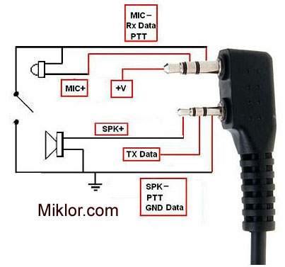
radio connector pinout
comm headset pinout (tp-120)
An externally hosted image should be here but it was not working when we last tested it.
1. Positive microphone channel
2. Positive earphone channel (mono)
3. Negative microphone channel
4. Negative earphone channel (mono)
- Status
- Not open for further replies.
- Home
- Live Sound
- Instruments and Amps
- Microphone pre amp