I think I remember reading a thread a while back about someone wishing there was a circuit to be able to calibrate light controlled resistors by microcontroller. I finally got around to putting some ideas together and its about time I stopped being a lurker on this site but its been a while since I lived in the analog world 😀 so some feedback would be appreciated.
The idea goes something like this:
-micro outputs 16 bit PWM to filters
-PWM to stable (hopefully noise free) variable DC control voltage
-DC to current for LED
For calibration:
-switches set to calibrate position
-micro runs calibration algorithm measuring LDR resistance (2^16 values at 12bits! 😛) (Rcalibrate, Rf, and Ri should be chosen based on chosen LDR)
For normal operation:
-switches set to operating position
-Tell the micro (via pot, rotary encoder, ir, i2c, serial, name your flavor) what resistance you want
-Bob's your uncle
Possible capabilities:
-user selectable min/max resistance
-user selectable law (linear, log, custom, etc.)
-with the micro in the schematic, up to 4 channels (LDRs) so series/shunt Lightspeed type preamp is possible
-I'll have to do some calculations, but one could probably get 1024 reliable resistance steps out of this. Maybe more!
Notes:
It feels like there should be a more elegant solution for a few things, but I just can't seem to put my finger on it. First, the filters. I want to try to keep the switching frequency for the PWM well above audio, and the filter well below audio. The Sallen-Key LP (set at 5Hz) was just the first thing that came to mind, but... 😕
Second thing is the manual switches for calibration mode. I would like to do something solid state, or even relays, but I don't want to get into the audio signal either. What I've been reading about LDRs is that the nice thing is that they have "no contacts." I envision the audiophile solution would to unplug whatever is at the LDR and insert some jumpers to calibrate, reverse for normal operation. What are the good solid state switches for preamps?
Also, I'm thinking about adding a thermal stabilising unit. From what I've read about LDRs is that they are rather temperature dependent. I might add a heater resistor and thermal sensor with associated circuitry to try to approach that problem.
Thanks in advance for any advice, suggestions, or questions!
PS On the schematic "LCR" should be "LDR"
Attachments
Last edited:
I did already what you are looking for: http://www.diyaudio.com/forums/analog-line-level/182294-sylonex-arduino-preamp.html.
It's working quite well. The volume is in use since a long time, but I should do more with the calibration like:
do it on regular intervals
choose in-and output impedance on the go
etc
This is all possible with programming only, but I'm more working on remote control by Android, coupling with Logitech remote (is working now) and other gadgets. Maybe I go back to the roots when I have more time.
Anyway if you want to develop from scratch, you're welcome for experience, or you can copy the design or parts of it.
You can try direct variable DC voltage to control the LDR led to make it simple.
I had desigh a ciruit used variable DC voltage to control the LDR led and get good
result. I had try many diffrent ways since last year,which included fix voltage
at 5, 3.3, 2.8, 2.5 volt, LM334 CCS, 24 step switch all need mach LDRs and I don't like that.
Then few months ago, I come up with the idea of direct used variable voltage
to control the LDR led with excellent result.
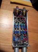
The circuit I desigh can drop in most LDRs,and easy to calibrated the channel balance to less than 1 DB . The ciruit had four trimmer used
for each LDR calibration.
first trimmer for 30 ohm to 100 ohm range adjustment, second one
for 100 ohm to 2K ohm range,third one used for adjusted of 2K to 80K range,the last one
for adjusted from 10K to over 100K. I can adjusted the resistance curve
easy, for example the shunt LDR I can adjusted the value to about 20% of
maximum value and series LDR to 80% of maximum value when set the
voltage control pot at the middle, the shunt /series LDRs act like A type
pot.
I had desigh a ciruit used variable DC voltage to control the LDR led and get good
result. I had try many diffrent ways since last year,which included fix voltage
at 5, 3.3, 2.8, 2.5 volt, LM334 CCS, 24 step switch all need mach LDRs and I don't like that.
Then few months ago, I come up with the idea of direct used variable voltage
to control the LDR led with excellent result.
The circuit I desigh can drop in most LDRs,and easy to calibrated the channel balance to less than 1 DB . The ciruit had four trimmer used
for each LDR calibration.
first trimmer for 30 ohm to 100 ohm range adjustment, second one
for 100 ohm to 2K ohm range,third one used for adjusted of 2K to 80K range,the last one
for adjusted from 10K to over 100K. I can adjusted the resistance curve
easy, for example the shunt LDR I can adjusted the value to about 20% of
maximum value and series LDR to 80% of maximum value when set the
voltage control pot at the middle, the shunt /series LDRs act like A type
pot.
Attachments
Sorry, I forget for 24 step switch you don't need match LDR, I try to used few
trimmer at a time and checked the trimmer value then replaced with a fix resistors,but the LDR are so sensitive at high resistance and they shift and drift, even I order a 1%
resistor kit which had over 500 diffrent vlaue but still can't found the right value so I give up for that idea.
trimmer at a time and checked the trimmer value then replaced with a fix resistors,but the LDR are so sensitive at high resistance and they shift and drift, even I order a 1%
resistor kit which had over 500 diffrent vlaue but still can't found the right value so I give up for that idea.
I did already what you are looking for: http://www.diyaudio.com/forums/analog-line-level/182294-sylonex-arduino-preamp.html.
It's working quite well. The volume is in use since a long time, but I should do more with the calibration like:
do it on regular intervals
choose in-and output impedance on the go
etc
This is all possible with programming only, but I'm more working on remote control by Android, coupling with Logitech remote (is working now) and other gadgets. Maybe I go back to the roots when I have more time.
Anyway if you want to develop from scratch, you're welcome for experience, or you can copy the design or parts of it.
That's great! I was thinking about Arduino too, but it didn't have the peripherals I wanted. I see you've added them. Really Cool! After looking around a little more for micros, I came across the Leaf Labs Maple (basically Arduino for ARM). I'll try to get one when finances allow 🙂
couldnt you adapt it to a rasberry pi to handle all the number crunching, remote, network access, source switching etc a bit more elegantly these days?
Qusp, I'm convinced that today the raspberry Pi would be a far better solution then an Ardiuno, but only if you're not afraid of a new platform lacking the huge info and amount of libraries that exist for the Arduino. The Arduino has more then enough power to handle everything, but the Raspberry could manage on top a squeezebox-client, avoiding the need for a PC to stream audio.
For sure I'll do this once, in a next life. But to start with, a small Arduino (you can find them from 12€ on) is more then enough.
For sure I'll do this once, in a next life. But to start with, a small Arduino (you can find them from 12€ on) is more then enough.
I like the way the raspberry pi looks, a lot of potential there, but I agree with oenboek. I think I'd be in over my head with the raspberry pi and it would probably be better to do the data collection/control circuitry through an offboard micro anyway then connect via spi, uart, or i2c.
- Status
- Not open for further replies.
- Home
- Source & Line
- Analog Line Level
- Microcontroller stepped LDR