Hi All,
We have been tasked to design a 3rd order high pass active Bessel filter, which I've correctly (I think) calculated the C and R values for. We have to use LM108 op amps.
My circuit is attached as a jpeg, when I try and run a transient analysis on microcap, I get 'Matrix is Singular' error.
Any ideas?
I need to use microcap to simulate the circuit and plot gain, phase, and group delay versus frequency over a range of 1Hz to 10kHz.
Can someone please help me?
Attachments

I don't see DC power sources, but have not used MCAP in nearly a decade so can't remember if they are implicit.
I think see the problem, way too much gain in the second stage. If you need gain and filtering simultaneously there is a circuit node you can tap for unity gain for the filter element, but since this appears to be a school project I will let you figure it out.
Hi Kevin,
Thanks for the response. I've looked at my gain resistors, and have recalculated, can you please have a look and see i've done it correctly?
As it is a school project, I do actually want to learn along the way.
My cutoff frequency is 60kHz,
and I worked out
K = 60 - 1.447 (I got 1.447 from 2 * ( a / (sqrt a^2 + b^2)) from the poles)
K = 58.553
K = 1 + R5/R4
So R4 should be about 58 times more than R5, right?
Read up on the limitations of Sallen-Key VCVS filters wrt achievable Q and stability 🙂
Might want to do a bode plot of this filter, I think that will illustrate the problem with the location of your poles.
Might want to do a bode plot of this filter, I think that will illustrate the problem with the location of your poles.
LM108 isn't unity gain stable in native form, it needs a compensation capacitor - so your input buffer is going to oscillate unless the model being used isn't a real LM108. Whether this is related to your matrix singularity seems doubtful though.
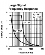
<edit> Note to teacher setting this - large signal frequency response for LM108 attached.
<edit> Note to teacher setting this - large signal frequency response for LM108 attached.
Attachments
Last edited:
Currently, I cant get a bode plot from microcap, but have gotten a pretty decent looking one from matlab using the poles taken from a table:
Second stage
1.0505 +/- 1.0025j
first stage
1.3270
so I used my second stage values to get K, and that shwat ive based it on. Do my poles still look wrong?
Second stage
1.0505 +/- 1.0025j
first stage
1.3270
so I used my second stage values to get K, and that shwat ive based it on. Do my poles still look wrong?
We got told to run the sim in microcap with LM108's, so I would assume that they would have been suitable for this purpose, but who knows, with my teacher.
You know how to read a frequency response plot? That's (post #7) culled directly from the datasheet and shows that if you need unity gain stability (which you do for the first stage buffer) the capability at 60kHz (your corner frequency) is lower than 1V peak. Your purported highpass will operate more akin to a bandpass where the low-pass effect is actually slewrate limiting (i.e. non-linear) unless the signal's kept well below 1V peak.
- Status
- Not open for further replies.
- Home
- Design & Build
- Software Tools
- Microcap error when simulating active filter