Michael Fearnley's vu meter driver circuit - How does it work?
Hi,
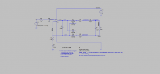
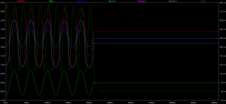
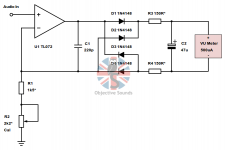
Recently I have read Michael Fearnley's article about vu meter driver circuit at the Objective Sounds website, and found it very interesting. I then simulated it with single rail power supply, and assembled the circuit. However, the actual circuit is not working as expected. There is not signal at the meter terminal. Can somebody help to point out where could I go wrong? Thanks a lot.


Jazzclassics
Hi,
Recently I have read Michael Fearnley's article about vu meter driver circuit at the Objective Sounds website, and found it very interesting. I then simulated it with single rail power supply, and assembled the circuit. However, the actual circuit is not working as expected. There is not signal at the meter terminal. Can somebody help to point out where could I go wrong? Thanks a lot.


Jazzclassics
You need to bias the opamp's input at 2.5V with a divider.
Note that 5V supply is not sufficient for a TL0XX. You should use a TLC271 for example.
Note that 5V supply is not sufficient for a TL0XX. You should use a TLC271 for example.
You need to bias the opamp's input at 2.5V with a divider.
And You need coupling capacitor in the feedback too.
Sajti
Thank you very much Elvee. I am actually using LM358 in place of the TL082. Is that a 20K/20K divider at the opamp's positive input ok for bias it?You need to bias the opamp's input at 2.5V with a divider.
Note that 5V supply is not sufficient for a TL0XX. You should use a TLC271 for example.
attached is the LM358 datasheet.View attachment LM358-D.PDF
Jazzclassics
And You need coupling capacitor in the feedback too.
Sajti
hi Sajti, thank you for your suggestion. Could you be more specific where to put that cap? Or maybe post an example circuit. I am lost here why i need a cap to block the DC in the feedback path, because I have not come cross such a circuit. Please enlightening me further.
hi Sajti, thank you for your suggestion. Could you be more specific where to put that cap? Or maybe post an example circuit. I am lost here why i need a cap to block the DC in the feedback path, because I have not come cross such a circuit. Please enlightening me further.
Hi,
I see on Your picture: C3 is the mentioned capacitor. Sorry, I just checked the original schematic. It will be OK with the divider, and C3.
Sajti
Hi Sajti, thanks for your reply. I fabricated the PCB and could not get it work, even with the voltage divider at the opamp's noninvert input. What else could be wrong?Hi,
I see on Your picture: C3 is the mentioned capacitor. Sorry, I just checked the original schematic. It will be OK with the divider, and C3.
Sajti
....Michael Fearnley's article about vu meter driver circuit at the Objective Sounds website....
It would have been kinder for all to link to the article you were reading, so we would know what you were talking about, and spot possible confusions.
Driving VU and other AC Meters - Simple High Performance Circuits
His "VU meter" circuits *omit* input and power connections. They do not work as shown.
His Fig 8, "Universal Volt-meter with selectable...." *does* have the input and power and bias connections completely detailed. Use that power/bias scheme to power-up the VU meter plan. The input needs a resistor to the C3 C2 node.
A very simple Vu meter driver using 2 BJTs 3 resistors 4 diodes.
https://www.diyaudio.com/forums/analog-line-level/283509-driving-vu-meters-2.html#post4547529
https://www.diyaudio.com/forums/analog-line-level/283509-driving-vu-meters-2.html#post4547529
A very simple Vu meter driver using 2 BJTs 3 resistors 4 diodes.
https://www.diyaudio.com/forums/analog-line-level/283509-driving-vu-meters-2.html#post4547529
Hi Mchambin,
thank you for your suggestion. that looks a simple circuit. Have you built it? How did it work?
I wonder that using one opamp is the simplist and cheapst way to drive two vu meters in a stereo setup. Do you think any of Michale Fearnley's circuit good to build? And I see many commercial circuits on ebay. Do you think any of them good to use?
I see you are using LTspice. Here I attach the simulation file for you to play with and if possible, feedback your valuable comments. Thank you.


View attachment VUmeterDriver_SingleRail.zip
Jazzclassics
It would have been kinder for all to link to the article you were reading, so we would know what you were talking about, and spot possible confusions.
Driving VU and other AC Meters - Simple High Performance Circuits
His "VU meter" circuits *omit* input and power connections. They do not work as shown.
His Fig 8, "Universal Volt-meter with selectable...." *does* have the input and power and bias connections completely detailed. Use that power/bias scheme to power-up the VU meter plan. The input needs a resistor to the C3 C2 node.
Hi
thanks for your post. Please could you point out how to make the circuit work? The simulation file is at the below link.
https://www.diyaudio.com/forums/sol...ys-vu-meter-driver-circuit-2.html#post5680877
Jazzclassics
Jazzclassics,
your first circuitry won't work at all, I'd say.
Best regards!
Hi Kay,
it is the truth. But the question is why it won't work? Why the simulation indicating it should work?
Please could you point out how to make the circuit work? The simulation file is at the above post.
Thank you!
This was built for 4 microphones preamplifier. This worked perfectly good right away.Hi Mchambin,
thank you for your suggestion. that looks a simple circuit. Have you built it? How did it work?
I wonder that using one opamp is the simplist and cheapst way to drive two vu meters in a stereo setup. Do you think any of Michale Fearnley's circuit good to build? And I see many commercial circuits on ebay. Do you think any of them good to use?
I see you are using LTspice. Here I attach the simulation file for you to play with and if possible, feedback your valuable comments. Thank you.
Jazzclassics
The 4 Vu meters monitor the preamplifiers on the 4 XLR output connectors. We used cheapo chinese Vu meters ( 650 ohm ) for their vintage look.
Later I figured, 4 diodes is overkill, a single diode would do the job as well.
You'e driving the meter with a rectified signal, which ist good, but you have a capacitor in series with it, which isn't that good.it is the truth. But the question is why it won't work? Why the simulation indicating it should work?
Please could you point out how to make the circuit work? The simulation file is at the above post.
Best regards!
It MUST be rectified. Yes, it should have NO capacitor.You'e driving the meter with a rectified signal, which ist good, but you have a capacitor in series with it, which isn't that good.
Best regards!
The original old time Vu meter driving circuit was: Two componants, a resistor in series with a germanium diode.
It MUST be rectified. Yes, it should have NO capacitor.
Correct.
The original old time Vu meter .... with a germanium diode.
The true VU meter used Copper Oxide rectifier.
For lack of any other great need, copper oxide rects have vanished from the market. Ge diodes are a poor replacement. Your higher-Z driver in the other thread is a good simple hack. It does not give proper damping for true VU meters, but you won't get that from low-cost meter movements anyway.
Hi Everyone,
I thought I'd contribute rather late, but contribute nonetheless and say that the circuits shown are mainly conceptual and are shown in their simplest form (i.e. without AC input coupling/DC decoupling) and assume that they will be connected to a low impedance (at DC and AC) source.
I will shortly modify the article to show this as I have been receiving a fair few e-mails from people who have built the circuits as shown as standalone units and in some cases haven't even referenced the input to ground.
I didn't think at the time of writing that people would be building them verbatim and without the peripheral components necessary for them to be operated as standalone units.
Cheers 😀 !
- Home
- Amplifiers
- Solid State
- Michael Fearnley's vu meter driver circuit