Long story short is I bought a cheap ebay class AB amplifier and its boards are kind of crap. I have two 300VA transformers with dual 33V and dual 12V taps. Time to DIY it!
I found Michael Beeny on Youtube and he has been doing some work with some off the shelf parts. He seems to know quite a lot and his video are very informative. They have been very helpful to me trying to figure this stuff out. If he is in here, please ping him and let him know he has inspired me to start my solid state amplifier journey. His latest build seems to utilize the same power by transformers have. I have the transformers and the heat sink enclosure. These are the two most expensive parts. I will mod the boards as he shows in his videos. I will post the parts I plan to use. I have questions which will come after the parts list
Link to Michael Beeny video.
1. 2x 300VA transformers - already have
2. One heat sink enclosure with RCA jacks, an on switch, RCA jacks, and Banana jack connections - already have
3. One set of L12-2 class AB amplifier Boards - 120w per channel
https://www.ebay.com/itm/144197833433
4. UPC 1237 speaker protection board
https://www.ebay.com/itm/403273875050
5. Soft start board - Need to know how to integrate this as I don't remember him showing where this goes in the video
https://www.ebay.com/itm/265073469343
6. 2x Rectifier filter power supply board - total of 80,000uf per channel
https://www.ebay.com/itm/125793069864
I do have a couple of questions that I hope someone here can answer:
1. Should I use one transformer per channel? I have two. Can I just combine the two 33V and two 12V taps and wire them into the same jack? I know, for example, that tying two legs of 120V together just shorts them out. I have exactly zero experience with toroids so not sure what happens here. If I can only pull one tap does it even make sense to run two toroids? Will only one tap pull only half the power? Again, no idea how these things are wound. I come from industrial automation equipment. We just use basic transformers.
2. How much capacitor bank do I need? The bank I put on there seems like it might be overkill. I am running 120V. I build my own speakers (you can find my stuff in the multiway forum). I usually make 4-6 ohm speakers. They will pull decent current. I also build bass heavy systems and prize bass dynamics above all else. I feel like going extra might be beneficial here.
3. How does the soft start integrate?
Hope ya'll can help. Let me know if I am missing anything. This isn't entirely ground up solid state but its a start.
Hi,
Mr. Beeny modified after my suggestions, which you can also read on my website.
It is important to note, that the latest iteration of the L12-2, the Rev_5 seemingly has major drawbacks in layout and other points.
See the videos of Mr. Beeny and the associated posts in the L12-2 threads hera at DIYaudio.
If You want to go the L12-2 route see that You stick with the Rev_2 or Rev_4! You can´t mod a crappy layout.
1. A single 300VA transformer -what voltages btw?- easily suffices for a pair of L12-2s.
It also doesn´t require a soft-start module, which is sensible if not a required for two 300VAs.
2. ok
3. See the above note ... stay with Rev_2 or Rev_4.
4. The 1237 is a good device capable of providing a couple of protection mechanisms.
Just look which ones are actually implemented on the board (DC-offset, AC-lines, Delay-On/Fast-Off, etc)
5. ok for two 300VAs, not necessary for one 300VA ... that is for 230V power lines
6. 80.000µF is ok if it fits into the casing.
Personally I would go for less, as more capacitance than required means more stress on the AC-line and rectifiers due to shorter and larger current peaks.
A Pi filter supply with smaller cap of 1.000-2.200F at the input, followed by a series inductance and a larger cap bank of even >=80.000µF will be less demanding and also reduces noise.
The board in the video utilized 2x4x6.800µF plus a speaker protect ... fully sufficient for a pair of L12-2s.
4x10.000µF plus speakerProtect has sufficiently large, but not too large capacitance plus a simple speaker protection.
I used similar 4x10.000µF boards wo the protection, utilizing Nover lytics successfully.
Same with ELNA lytics, which are also seen with 6x10.000µF (which is plenty to supply a pair of L12-2s with).
Keep in mind how the protection boards are powered.
Does it need a dedicated dc-supply or can it be powered from the transformer´s AC-secondary?
The latter eases matters considerably.
jauu
Calvin
You can size filter caps roughly based on mains frequency f, speaker impedance R, and dB loss (compared to infinite caps) thus:
C (in farads) = 4 / (R * F * dB).
So for 0.5dB of loss, 4 ohm speaker, 60Hz mains you get 33mF (33,000uF)
0.08F would give 0.2dB of loss
This is based on the drooping of the supply voltage over a 1/2 cycle of mains frequency assuming a full-scale output signal.
The factor of 4 is more accurately given by 10/ln(10). I'll leave this as an exercise to the reader!
The notable thing is the cap value doesn't depend on the amplifier voltage rail or power, just the load impedance and mains freq.
If you have a SMPS you don't need these big filter caps (or rather they are much smaller and built in to the SMPS).
Good to know, will still to REV2 or REV4. Is there another board you suggest over the L12-2 that uses the same input voltages?It is important to note, that the latest iteration of the L12-2, the Rev_5 seemingly has major drawbacks in layout and other points.
See the videos of Mr. Beeny and the associated posts in the L12-2 threads hera at DIYaudio.
If You want to go the L12-2 route see that You stick with the Rev_2 or Rev_4! You can´t mod a crappy layout.
The input is 120v. The two pairs of output taps I measured at 33-36V and 12-13.1V. My shop has slightly has voltage output. I also have made a small transformer than can buck 9% voltage to drop from the 125V my home puts out to 109.5V. With any of the inputs its range is 33-36V and 12-13.1V.1. A single 300VA transformer -what voltages btw?- easily suffices for a pair of L12-2s.
It also doesn´t require a soft-start module, which is sensible if not a required for two 300VAs.
No benefit to using both transformers I take it.
I do not have enough knowledge about the board to know what protection module to use. If there is a different speaker protection board for my purposes, please let me know.4. The 1237 is a good device capable of providing a couple of protection mechanisms.
Just look which ones are actually implemented on the board (DC-offset, AC-lines, Delay-On/Fast-Off, etc)
Understood5. ok for two 300VAs, not necessary for one 300VA ... that is for 230V power lines
Ok, got it. So too much capacitance can just cause noise.80.000µF is ok if it fits into the casing.
Personally I would go for less, as more capacitance than required means more stress on the AC-line and rectifiers due to shorter and larger current peaks.
A Pi filter supply with smaller cap of 1.000-2.200F at the input, followed by a series inductance and a larger cap bank of even >=80.000µF will be less demanding and also reduces noise.
The board in the video utilized 2x4x6.800µF plus a speaker protect ... fully sufficient for a pair of L12-2s.
4x10.000µF plus speakerProtect has sufficiently large, but not too large capacitance plus a simple speaker protection.
I used similar 4x10.000µF boards wo the protection, utilizing Nover lytics successfully.
Same with ELNA lytics, which are also seen with 6x10.000µF (which is plenty to supply a pair of L12-2s with).
Keep in mind how the protection boards are powered.
Does it need a dedicated dc-supply or can it be powered from the transformer´s AC-secondary?
The latter eases matters considerably.
I would defer to your judgement on which to use, please advise. The 4x10,000 w/ protection, the Nover cap board, or the Elna Cap board.
I don't see why the speaker protection boards couldn't be powered by the 12v taps off of the toroid. I assume this is why they were wound this way in the first place.
What is your website? I would like to peruse.which you can also read on my website.
I am open to an entirely different setup and entirely different boards. This is just what I could find searching around that seemed to work with I already have. I have an entire engineering firm fabrication studio and an entire engineering firm embedded department lab at my disposal. My day job is managing the fab studio for the firm. I want for very little outside of knowledge of what makes up a good amplifier. I just need guidance. The rest I can fabricate
Is the "F", the frequency, of his calculation based on the F3 of the system? I apologize, I am not familiar with the term "mains frequency".You can size filter caps roughly based on mains frequency f, speaker impedance R, and dB loss (compared to infinite caps) thus:
C (in farads) = 4 / (R * F * dB).
So for 0.5dB of loss, 4 ohm speaker, 60Hz mains you get 33mF (33,000uF)
0.08F would give 0.2dB of loss
This is based on the drooping of the supply voltage over a 1/2 cycle of mains frequency assuming a full-scale output signal.
The factor of 4 is more accurately given by 10/ln(10). I'll leave this as an exercise to the reader!
The notable thing is the cap value doesn't depend on the amplifier voltage rail or power, just the load impedance and mains freq.
If I have a 4 ohm speaker, an F3 of 40, and a targeted loss of 1db I get 25,000uf. I would think the lower the frequency I target, the more cap reserve power I would want. This calculation, based on my interpretation of "F", seems to point to the opposite conclusion.
I have a couple of these laying around the shop but they are all 24V. Not enough to power the L2-12 boards. I would think a toroid is more beneficial to use in this application than a switching power supply no?If you have a SMPS you don't need these big filter caps (or rather they are much smaller and built in to the SMPS).
Calvin,
I am building a 6 ch amp with the Rev2 boards. How would you suggest to approach a power supply for all modules together? I won‘t be needing more than 50w/8ohm from each (actually MUCH less on four of them). How about regulated supplies or choke input (or small input cap + choke)?
I am building a 6 ch amp with the Rev2 boards. How would you suggest to approach a power supply for all modules together? I won‘t be needing more than 50w/8ohm from each (actually MUCH less on four of them). How about regulated supplies or choke input (or small input cap + choke)?
Swak,Calvin,
I am building a 6 ch amp with the Rev2 boards. How would you suggest to approach a power supply for all modules together? I won‘t be needing more than 50w/8ohm from each (actually MUCH less on four of them). How about regulated supplies or choke input (or small input cap + choke)?
Where are you finding all of the revisions of the boards? I am only seeing the version 5 videos and not an schematics or directions for the other revisions
Hi,
the versions prior to the infamous Rev_5 can be discriminated by their Layout.
The former versions had 3pcs TO126 transistors mounted in the middle of the upper edge of the PCB on a common cooling track.
Rev_5 moved the driver transistors to cooling fins close to the output transistors.
And here´s Mr. Beeny´s thread and video that started the uproar: NEW L12/2 version 5. I have just received a pair of these amplifiers, I stopped testing because the boards are unstable
And here´s My website
jauu
Calvin
Its the AC frequency of the electricity mains. 50 or 60Hz depending on where in the world you are, 400Hz on aircraft. The filter caps have to hold up the DC rail inbetween half cycles of the mains waveform.Is the "F", the frequency, of his calculation based on the F3 of the system? I apologize, I am not familiar with the term "mains frequency".
Ahh, got it. So 60 hz for meIts the AC frequency of the electricity mains. 50 or 60Hz depending on where in the world you are, 400Hz on aircraft. The filter caps have to hold up the DC rail inbetween half cycles of the mains waveform.
So are these boards not worth modifying and utilizing? It seems like you are less than impressed with them.the versions prior to the infamous Rev_5 can be discriminated by their Layout.
The former versions had 3pcs TO126 transistors mounted in the middle of the upper edge of the PCB on a common cooling track.
Rev_5 moved the driver transistors to cooling fins close to the output transistors.
And here´s Mr. Beeny´s thread and video that started the uproar: NEW L12/2 version 5. I have just received a pair of these amplifiers, I stopped testing because the boards are unstable
And here´s My website
I bought mine form a forum member that had bought them long ago. It has the ferrite left of center, which identifies rev2.Where are you finding all of the revisions of the boards?
Calvin's site is very helpful and was what got me interested in this amplifier.
Hi,
I had a conversation with Mr.Beeny and he told me that in his and his mate´s eyes they found the layout to be real cr***.
I understand their video and the following thread here as a way to get the thing at least somehow going, so that You don´t need to bin it.
The modifications just achieve that .... they don´t make a flawed item a decent amp.
jauu
Calvin
@swak it wasn´t me ... it was already kaput 😆
Well that doesn't seem to be worth the time. If it's a flawed design from the beginning I don't see a point in try to fix it. I would rather take something stable and tweak it to improve further.they found the layout to be real cr***.
There are a lot more board out there and I could always make one of the wolverine board sets.
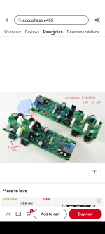
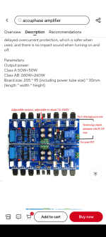
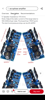
These 3 board in the attachments are cheap enough that they might be fun messing with.
Attachments
- Home
- Amplifiers
- Solid State
- Michael Beeny Build - Capacitance question