Hi Everyone
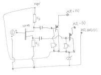
I've a little Mic Preamp Circuit for a large Diaphragm Capacitor Capsule.
Now I've seen in a Youtube-Video, that they use a differential amplifier.
I've added this also to my circuit, but they use a Zener-Diode from Ground to VCC (48 Volts).
But they didn't mention the specification for choose the right one.
It works without the Zener-Diode, so is my question do I need this or not? And why?
And how to choose the right one?
I need the 48 Volts also for the polarization of the Condenser Capsule.
I get the 48 Volts from Phantom-Power over the XLR (Pin 2 + 3 -> 6.8kOhm -> Capacitor).
I attached the simplyfied Schematic.
Thank you for your help.
Attachments
Zener diodes are very noisy and you'd only use them in a microphone preamp if parallelled with a large capacitor. For a simple emitter-follower you'd not really need to regulate the voltage, just decouple.
The JFET input stage however may well need its voltage limited to reduce hot-carrier injection effects - 12--20V perhaps?
The JFET input stage however may well need its voltage limited to reduce hot-carrier injection effects - 12--20V perhaps?
Thank you for your Answer.
You mean, I should also decouple from the Emitter to the XLR?
Yes, this Part is missing, I wan't also add a Overvoltage-Protection vor Voltage-Spikes at a later time.
You mean, I should also decouple from the Emitter to the XLR?
Yes, this Part is missing, I wan't also add a Overvoltage-Protection vor Voltage-Spikes at a later time.
Hi Jan
Maybe I didn't got it right from my source for this Differential Amplifier Idea.
But I understood, that so I get a better symetrical Signal (Balanced) for the XLR connection?
I got the Idea from this Youtube-Video:
They talk about it at beggining of Minute 8 further..
Maybe I translated it wrong, because it's not my native language ;-).
Thank you.
Lukas
Maybe I didn't got it right from my source for this Differential Amplifier Idea.
But I understood, that so I get a better symetrical Signal (Balanced) for the XLR connection?
I got the Idea from this Youtube-Video:
Maybe I translated it wrong, because it's not my native language ;-).
Thank you.
Lukas
I think you got it right. I never saw such a circuit, it is neat.
I am not sure about the noise performance though.
Remember: a balanced connection is used to lower loise pickup on the line.
For that to work, the source- and load impedances at the both ends of the line must be equal, preferably over the audio band.
The signals on the line do not have to be symmetrical around ground - in fact, the whole idea is that ground plays no role anymore!
That again means that you can feed the balanced line with a single ended source, as long as the source impedance seen by both lines are equal.
For instance, you could have a single ended source with 100R output impedance feeding XLR+ and connect XLR- to ground by 100R.
That will accomp[lishe the purpoase of the balanced connection.
Single ended source normally have lower noise than balanced sources.
Jan
The +48 VDC from phantom is supplied "down the wire" from a pair of 6K8 Ohm resistors, so, loaded, there's never actually 48 VDC at the microphone. That Zener may actually be regulating, but it can't be to +48 VDC. In effect, for DC the input FET is in series with the push-pull output followers. Folk were doing even cooler stuff before electrets and semi-cons, but it didn't fit on three wires.
All good fortune,
Chris
All good fortune,
Chris

If you watch the video, you see that the zener is added almost in passing but the customary series R to the supply is omitted.
They were concentrating on the balanced stage.
That zener should be considered as a conceptual thing, and needs some more thought to make it functional.
They do add a cap in // of the zener later in the video.
Even later, towards the end, they show that what looked as psu voltage on the left side is actually coming from the 48V though a series of Rs, so that sets the zener current.
Only remaining question is the zener voltage - my guess is 6V or so.
Jan
Last edited:
Here is possibly the original circuit and has a high voltage generator for condenser capsules .

Also have a look at mp3forkidz.com/mic/ for various microphone circuits including a simplified version of this for electret capsules
Also have a look at mp3forkidz.com/mic/ for various microphone circuits including a simplified version of this for electret capsules
Last edited:
It shows a 6.2V zener, so my guess was only 0.2V off ;-)
Jan
Jan
maybe I should open a new Topic for this Question, but I have another Question:
I've tested my descripted Circuit, and it works, mainly.
The Problem is, that it's getting automaticaly louder and louder (in about 5-10 Seconds), the amplification from the Mic and also the Noise.
Why is that? It has to come from the PNP-Transistors, because, if I remove them, this doesen't happen.
I used for the Resistor "R" 100k.
Thank you for your Help.
Lukas
Hi
After some time I finished this Project and I like to share my solution:
First: I decided not to use the Zener Diode.
In my last comment I mentioned my problem with the Feedback. After I used smaller Capacitors (68 NF) it disappeared.
After all this is my Circuit:

For the Transistors it is essential to select best matching Transistors with the same hfe.
I buyed about 50 pieces of the A1015 and tested them.
I didn't had an hfe-Tester so I helped me out with this Test-Circuit:

This is my Product:

I didn't have special Tools for produce a nice Housing and I didn't want to use a buyed one.
So I went to the hardware store...
I use it for Audio-Communication in MS Teams and it does it's job well.
But I want to test it in a Recording Session in the near Future.
I don't expect a great quality, but if I needed that, I would buy one for the Job 🙂.
Thanks again for helping me!
After some time I finished this Project and I like to share my solution:
First: I decided not to use the Zener Diode.
In my last comment I mentioned my problem with the Feedback. After I used smaller Capacitors (68 NF) it disappeared.
After all this is my Circuit:
For the Transistors it is essential to select best matching Transistors with the same hfe.
I buyed about 50 pieces of the A1015 and tested them.
I didn't had an hfe-Tester so I helped me out with this Test-Circuit:
This is my Product:
I didn't have special Tools for produce a nice Housing and I didn't want to use a buyed one.
So I went to the hardware store...
I use it for Audio-Communication in MS Teams and it does it's job well.
But I want to test it in a Recording Session in the near Future.
I don't expect a great quality, but if I needed that, I would buy one for the Job 🙂.
Thanks again for helping me!
- Home
- Source & Line
- Analogue Source
- Mic Preamp with Differential Amplifier, which Zener Diode?