The preamp goes LL1538 - EF86 diode biased(with local negative feedback) - AC coupled ECC81 cathode follower - 47k gain pot - ECC81 diode biased common gain stage - DC coupled 5814A (ECC82 equivalent) white cathode follower - 10uF coupling cap => audio interface is a 10k load. There is no noise floor to speak of, even using an sm58 my computer's quiet fan (in another room) drowns out any hiss and there is zero hum. The amazing lack of self noise genuinely surprises me, as this prototype layout has been twisted and warped so many times, it's a complete mess inside. I can't wait to rebuild with a proper layout and it already sounds better than any other pre I own.
Andy
I have a particular interest in tube mic pre design. Would you be prepared to post a schematic of your mic pre?
Cheers
Ian
The screen supply comes from a 68k/33k voltage divider with a 100n bypass cap going to the cathode. This (from 250V b+) gives a stiff 75.5V screen voltage.
I could use zener diodes instead to reach the same screen voltage, but with all the local negative feedback wrapped round this stage and diode biasing, it's very transparent already.
I'll have a schematic drawn up and posted within the next week, a lot on my plate right now. I'm sure you guys can point out some flaws!
Last edited:
unless I have misunderstood something, that looks like a 3db point at about 100Hz; how did you calculate the screen cap?
I wouldn't be too surprised if the -3dB point was where you said, all the negative feedback may have compensated for it. Where possible, I tend to avoid calculations and instead go by ear and/or visual analysis. Too many equations make my eyes glaze over and then I just turn to example circuits as a starting point and then tweak away. Typical component tolerances 'almost always' ensure that my way gives better results than any calculations. (I'm not a pro, and don't pretend to be!)
This pentode stage is proving difficult though, I've just put my zeners back in(3x1N5359B for ~72V) and the noise floor has gone through the roof (probably why I got rid of them in the first place). Merlin Blencowe's book on preamp design suggests that 100n should be enough to tame the hiss, but I've just clipped in a 2.2uF cap on top of the existing 100n and that has reduced it to a faint and dull hiss. Still more than with the simple voltage divider. (btw the zeners and bypass cap go to the cathode, which has 2x1N4007 diodes and a 100n bypass cap)
I'm sure I've read somewhere that zeners can oscillate and self destruct with too large a capacitor. Is that true? And how large is too large?
Last edited:
You can make your resistor divider perform better by buffering it with a transistor emitter follower.
Shoog
Shoog
Finally, here is the schematic as the preamp is now, not added the transformerless option yet, but will get on to that as time allows.
Any comments/criticisms are welcome!
 [/url]DMP-1g schematic by TheAndyroid, on Flickr[/IMG]
Any comments/criticisms are welcome!
There are several things you might consider:
1. R20 is in series with the input signal from the noise point of view and may seriously compromise the noise performance of the circuit. You might want to look at an alternative arrangement for setting the gain of the first stage.
2.Similarly R23 is in series with the sihnal and only adds to the noise. A grid stopper is not necessary with the EF86.
3. XLR pin 1 should go to chassis not 0V. )V and chassis should be connected at one point only, close the the mains inlet.
4. Similarly the 0V of the phantom power should be connected to pin 1 of the XLR and not directly to HT 0V.
5. The 0V phantom is taken from the wrong side of R9/R14.
6. You have snubbers on the diodes of the HT supply but not on those of the phantom supply.
7. R5 and R6 are too large. Most tubes that specify the resistance from heater the cathode state it should be not more than about 22K.
Cheers
Ian
Thanks for taking the time to look through my schematic, I've made a few changes to the preamp and schematic according to your suggestions.
1, The negative feedback round the EF86 creates a 'virtual earth', so R20 is effectively the load resistor that sets the input impedance of the mic preamp. It's a 2W metal film and 38k doesn't seem that big to me. I come from the guitar amp world where 68k is the norm, and HUGE amounts of gain are used with little noise trouble. I think I'll keep it like this, it's part of the NFB circuit which has helped in many ways.
2, 1k is again only very small, I wouldn't expect any thermal noise. Why do you say the EF86 doesn't need a grid stopper?
3, I have read in several places that separating the main filter ground from the preamp ground is a good idea and I have noticed the noise benefits in several of my amps. Grounding the preamp at the input and the power supply near the mains inlet has always worked for me.
4, So far, no problems. The star ground is actually on the jack socket and the XLR is right next to that. So, it near enough does go to pin 1. Kinda'... When I
build more of these, I will do it directly to pin 1.
5, The schematic didn't reflect the actual grounding scheme in the preamp. I think it does now though 🙂 It was originally grounded before R9/R14, and there was no direct connection between R10 and C13's cathode. C13's cathode was connected to pin 1.
Now there is just one phantom power ground which goes to pin 1. Not sure which is the best way, I cant tell the difference.
6, The snubbers prevent switching noise from getting into the heater supply. The phantom power supply comes from a different transformer, so snubbers are not needed. Or am I missing something?
7, R5 and R6 are now safe, thank you! What would have happened if I left them as they were? The preamp has had several hours use with R6 being far too big, luckily all seems to be fine.
Here's an updated schematic:
Thanks for taking the time to look through my schematic, I've made a few changes to the preamp and schematic according to your suggestions.
1, The negative feedback round the EF86 creates a 'virtual earth', so R20 is effectively the load resistor that sets the input impedance of the mic preamp. It's a 2W metal film and 38k doesn't seem that big to me. I come from the guitar amp world where 68k is the norm, and HUGE amounts of gain are used with little noise trouble. I think I'll keep it like this, it's part of the NFB circuit which has helped in many ways.
Everything you say is correct. However, because of the virtual earth, the 38K is effectively in series with the input from the noise point of view. A 150 ohm microphone reflected to the secondary of the Lundahl will look like 3750 ohms and represents the thermal noise component of the source. The 38K in series with it is 10 times bigger so its noise will be 10dB higher. If you signal level is sufficient then it probably does not matter. Just be aware that this is not the lowest noise configuration.
The 68K resistors commonly found at the input of guitar amps serve, in combination with the Miller capacitance of the input stage, to limit the frequency response. The singal level from a guitar is easily 20dB higher than you are likely to see at the secondary of the Lundahl so noise is much less of an issue.
2, 1k is again only very small, I wouldn't expect any thermal noise. Why do you say the EF86 doesn't need a grid stopper?
You are right. In the oversll scheme of things, the 1K is not a significant source of noise. Grid stoppers are only needed for high gm tubes which the EF86 is not.
3, I have read in several places that separating the main filter ground from the preamp ground is a good idea and I have noticed the noise benefits in several of my amps. Grounding the preamp at the input and the power supply near the mains inlet has always worked for me.
4, So far, no problems. The star ground is actually on the jack socket and the XLR is right next to that. So, it near enough does go to pin 1. Kinda'... When I
build more of these, I will do it directly to pin 1.
5, The schematic didn't reflect the actual grounding scheme in the preamp. I think it does now though 🙂 It was originally grounded before R9/R14, and there was no direct connection between R10 and C13's cathode. C13's cathode was connected to pin 1.
Now there is just one phantom power ground which goes to pin 1. Not sure which is the best way, I cant tell the difference.
For my take on handlig grounding in tube mic pres and mixers check this out:
http://www.ianbell.ukfsn.org/EzTubeMixer/docs/EzTubeMixer/SimpleMixer/grounding101v2.pdf
My experience has been that diode switching noise often gets into the HT supply as well and can originate from any rectifier in the supply so I habitually snub all bridges. I usually use a single 100nF film cap across the ac input to the bridge.6, The snubbers prevent switching noise from getting into the heater supply. The phantom power supply comes from a different transformer, so snubbers are not needed. Or am I missing something?
7, R5 and R6 are now safe, thank you! What would have happened if I left them as they were? The preamp has had several hours use with R6 being far too big, luckily all seems to be fine.
Probably nothing would have happened. I only realised this a few months ago and prior to that had used much higher values without any obvious problem.
The phantom supply is still not quite right. I think C13 and C14 are supposed to be between the phantom output and the phantom ground rather than across R10.
Cheers
Ian
He would need another gain stage after the EF86 in order to change his loop feedback to the noninverting input. He could also make the feedback resistor variable, as is done in many other mic preamps.
He would need another gain stage after the EF86 in order to change his loop feedback to the noninverting input. He could also make the feedback resistor variable, as is done in many other mic preamps.
Or he could take he NFB from the CF output and reduce the feedback network components by a factor of 10 or more. Rupert Neve did something similar in one of his early tube mixers.
Cheers
Ian
Or he could take he NFB from the CF output and reduce the feedback network components by a factor of 10 or more. Rupert Neve did something similar in one of his early tube mixers.
Cheers
Ian
Yes, of course he could do that Ian. It would reduce noise by a large factor. If he did that, it would also be far better if he DC coupled the CF to the plate of the EF86. That way, he could avoid an extra time constant in his feedback loop.
Great ideas on this thread!
Yes, of course he could do that Ian. It would reduce noise by a large factor. If he did that, it would also be far better if he DC coupled the CF to the plate of the EF86. That way, he could avoid an extra time constant in his feedback loop.
Great ideas on this thread!
Which is exactly what Rupert Neve did. Here is a screen shot from part of the schematic for his tube mixer.
Cheers
Ian
Attachments
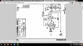
That's a very clever design! I never thought to get the screen voltage for the pentode from the cathode follower. I'm a little confused about the feedback arrangement. Is the 100k resistor the second element of the voltage divider? (which means the feedback signal goes through the secondary of the transformer) Or is the 3.3k the second element? Thanks for sharing.
That's a very clever design! I never thought to get the screen voltage for the pentode from the cathode follower. I'm a little confused about the feedback arrangement. Is the 100k resistor the second element of the voltage divider? (which means the feedback signal goes through the secondary of the transformer) Or is the 3.3k the second element? Thanks for sharing.
The 100K is right across the transformer and so it is the secondary load. It's difficult to tell the transformer ratio, but if is is 10:1 then the 100K will look like 1K at the primary which was probably a typical load for a 200 ohm source in those days. The 3.3K is the second element of the NFB and replaces the 38K in the OPs circuit. A 200 ohm source will look like 20K at the secondary so its noise will swamp that from the 3K3.
The screen voltage connection from the CF output has been done many times before but this was the first time I came across it. Rupert had some neat circuits even back then.
Cheers
Ian
Last edited:
I have consistently found in simulation that choke loads produce lower noise gain circuits than anything else (like mosfet constant current source, resistors, etc.). Now that I have a pair of 100H/10mA chokes, I hope to experiment with them in real life to verify my findings. Obviously, these things have to be shielded from hum fields, but otherwise they appear to have significant advantages in regards to SNR. The only down side is that they have limited bandwidth and have a little bit higher distortion that is also frequency dependent. Certainly, they cost more than a resistor also. But, for circuits where low noise is the highest criteria, then I would think a choke load would be a good choice. I have a demonstration simulation up on my blog about this. Here's hoping!
- Status
- Not open for further replies.
- Home
- Live Sound
- Instruments and Amps
- Mic preamp input transformer alternative?