Hi all,
a friend asked me for a pair of "quite cheap but decent" preamps for dynamic mics (sm57/58, e825/835 and the like). That rules out transformer input preamps. They will be used to provide additional mic inputs into consoles with extra unbalanced line inputs (I have small cards with drv134 for balanced out if needed). It is also best if I can avoid exotic/difficult to get parts and stick to commonly available parts (I've already the 4403).
So, I put together a few datasheets and app notes (mostly THAT published stuff: "AES129_Designing_Mic_Preamps.pdf" , "Galo_THAT_Line_Dr_ Rx.pdf" ), mixed it with the common trick to run the ne5534 with a class a output stage from the compensation pin and came out with this:
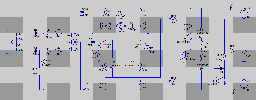
It should provide about 50db of gain. It should be short-circuit proof, input protection is already there if phantom power has to be added (best to get 100v caps for C4-C5).
From experience, I certainly must have made some mistakes I'd be thankful for any input before I start drawing the pcb.
🙂
PS: apologies to the mods if this is the wrong forum. Please feel free to move it if necessary. 😱
a friend asked me for a pair of "quite cheap but decent" preamps for dynamic mics (sm57/58, e825/835 and the like). That rules out transformer input preamps. They will be used to provide additional mic inputs into consoles with extra unbalanced line inputs (I have small cards with drv134 for balanced out if needed). It is also best if I can avoid exotic/difficult to get parts and stick to commonly available parts (I've already the 4403).
So, I put together a few datasheets and app notes (mostly THAT published stuff: "AES129_Designing_Mic_Preamps.pdf" , "Galo_THAT_Line_Dr_ Rx.pdf" ), mixed it with the common trick to run the ne5534 with a class a output stage from the compensation pin and came out with this:
It should provide about 50db of gain. It should be short-circuit proof, input protection is already there if phantom power has to be added (best to get 100v caps for C4-C5).
From experience, I certainly must have made some mistakes
I'd be thankful for any input before I start drawing the pcb.🙂
PS: apologies to the mods if this is the wrong forum. Please feel free to move it if necessary. 😱
Attachments
Why C1 D6 and D7? They appears to be not necessary. Also it appears too complex for a simple pre-amplifier, too much components. Why the high pass Tee filter at the input? Why not a single cap?
Why C1, D6 and D7?
C1 is needed to keep the output offset of the first gain stage reasonably low. Can't skip this one. D6 and D7 are reverse-protection diodes which prevent bad smell if the PSU is wired wrong, and have some secondary duty for phantom power protection.
Why the high pass Tee filter at the input? Why not a single cap?
The intention behind this is to keep the 'lytics forward biased all the time, and to reduce distortion. With the very low signal levels found at the input of a mic preamp I agree that this is overkill for such a simple design. Same applies for the extra class A buffer of the NE5534.
Other suggestions:
* I'd move R20/R21 ahead of C3/C8, so they help a bit with RF protection too.
* To improve low-frequency CMRR I'd make R5/R6 22k, and add a 4k7 resistor in parallel with C9 (makes mismatch of the phantom blocking caps less detrimental to CMRR).
Samuel
Thanks for the comments. Nothing to add to what Samuel Groner just said.
Yes, it's a bit complex as is. Prejudice would push me to keep the biased electrolytics but I'll drop the output buffer. I'll also change the input resistors as suggested. I guess that changing the opa134 by a cheaper tl071 for the servo should be allright.
Only question left is about r20-21: THAT app notes suggest those resistor to limit the current in case of phantom fault and reduce the strain on the diodes. Should I move them in front of c3/c8 or put another pair of 4.7 resistors in front of c3/c8 ?
C1 is needed to keep the output offset of the first gain stage reasonably low. Can't skip this one. D6 and D7 are reverse-protection diodes which prevent bad smell if the PSU is wired wrong, and have some secondary duty for phantom power protection.
Hi Samuel. I don't see why does he need this cap, I believe to use a simple differential amplifier removing all components in the emitters, and using a CCS.
The intention behind this is to keep the 'lytics forward biased all the time, and to reduce distortion. With the very low signal levels found at the input of a mic preamp I agree that this is overkill for such a simple design. Same applies for the extra class A buffer of the NE5534.
I strongly dislike this idea. This introduces supply noise in the audio path, and causes severe peaks in the output when turning on or off. as cap's charges or discharges. Moreover, you can put a 47 µF bipolar and eliminate the entire network. Or you can use a small 1.5V cell and to overcome this trouble.
Also dislike diodes in series. It is preferable to use parallel transil or tranzorb diodes plus fuses, this way 3 protection in 1 components, and no drop in the supply.[/QUOTE]
Last edited:
WRT C1: it's part of a well-established and proven topology, no need to reinvent the wheel here. I don't want to sound defensive, but I'm not aiming for something "new".
WRT biased electro: you can use up to 1meg to bias the caps (as done by SSL). The charge/discharge will be so slow that it won't appear on the output at turn on. In fact, the servo is more of a problem, as it is very slow and will probably cause a peak at startup. A muting transistor with a 2 sec startup delay might be useful here.
Forgot: good bipolar are sadly a rather exotic component. I can get plenty of cheap good polar caps (pana FC or the like). Much more difficult for the bipolar (unless you accept no name stuff or accept to pay a lot more)
Last edited:
Only question left is about R20-21: THAT app notes suggest those resistor to limit the current in case of phantom fault and reduce the strain on the diodes. Should I move them in front of C3/C8 or put another pair of 4r7 resistors in front of C3/C8?
They protect from phantom faults also in front of C3/C8, so you don't need additional resistors.
I don't see why does he need this cap, I believe to use a simple differential amplifier removing all components in the emitters, and using a CCS.
Again, the cap is needed to prevent excessive DC offset. If the Vbes mismatch by 10 mV and gain is 40 dB, we have 1 V at the output which is no good. The emitter degeneration can't be removed as it sets gain. This is different from an opamp input.
This introduces supply noise in the audio path.
Yes, that's true. At least it is strongly attenuated--with a 200 Ohm mic ~60 dB.
Also dislike diodes in series.
It has some merits in this context. With a phantom power short the rails may rise considerably, and the series diodes protect other circuitry connected to the same PSU from excess voltage. I wouldn't use the series diodes for a super-dupy low-THD design either, but here I see little to worry.
Samuel
Doug Self has a few mic pre circuits in his Small Signal Audio Design book
points out that using op amp gain in balanced loops feeding back to the Q emitters gives better linearity
your CFA is a start but runs the 2N4403 at too low current for the mic load - although it looks to me like less than 1 dB noise figure improvement is possible
I'm dubious that the 5534 hack beats simply using a good modern op amp
which can be ordered from Digikey at the same time as the 80 cent Panasonic SU 100 uF 50 V bipolar caps they have in stock
Rant alert: Digikey will cost me about as much in shipping+duties than the total of the parts. RS and Farnell can only sell to business in France and Belgium (legal issues of unfair competition and so on). Only options are small electronics shops with awful parts selection or overpriced audiophile shops... Getting decent parts is a true pain around here. At least there's reichelt.de for the common stuff. /end of rant and whining
At jcx: On a more useful tone, I'll get a look to Self, I know a library where they have a copy.
WRT to the current running through the 4403, I looked at a few existing preamps, which run at 1ma for the 2n4403 and 3 to 4ma for the other transistor in the cfp. You would double it ? Current draw isn't a big concern.
I think the ~1 mA is spot on. Most dynamic mics have an impedance of several hundred ohms (I recall 600 Ohms for an SM57) in the critical frequency range of some kHz. The nominal impedance quoted on the datasheet is actually the DC resistance which is of modest interest only.
Likely the opamp doesn't matter at all WRT distortion. The frontend will dominate.
Samuel
I'm dubious that the 5534 hack beats simply using a good modern op amp.
Likely the opamp doesn't matter at all WRT distortion. The frontend will dominate.
Samuel
Thanks everyone for the inputs. 🙂
I'm gone until Monday in a place without internet connection, so please excuse me if I don't answer any new post until then.
I'm gone until Monday in a place without internet connection, so please excuse me if I don't answer any new post until then.
After a look at D. Self's book, an another look at this topic and another look yet at my parts bin (in which a few 30VDC/500ma printers wallwarts could be found), I came back with this, which is just an adaptation of the old Benchmark schematic:
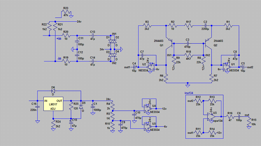
Does it seem a better choice ?
PS: r17 is a 5K reverse log pot
Does it seem a better choice ?
PS: r17 is a 5K reverse log pot
Attachments
Quick correction (can't edit...): rather than an ina134, an ina137 should be used to get some gain at the output stage (or an opa134 could be used and then r11-14 should be 10k and 33K or so).
Other detail: ne5534 are shown (because that's what is in my software) but ne5532 will be used.
Other detail: ne5534 are shown (because that's what is in my software) but ne5532 will be used.
Looks good to me (just a quick look though). U5 is unnecessary, as its output drives a high-Z node only. So you'll get away with two NE5532. I'd make R11-R14 smaller for some noise benefit at low gains, say 3k3. I don't think that you'll need another gain stage at the output, this topology does pretty well up to +60 dB (but it is difficult to implement the gain control with a pot, as at high gains the resistance need to be very low).
Samuel
Samuel
Going back to the first one, though the comments apply to this one too, it would be nice to see a known filter on the input, even if it is at a MHz or so. So rather than than 10 ohms, have 330 or 470, unless there is some reason you'd rather not. With just 10 ohms your top end pole is at the mercy of whatever the output impedance of the mic is and will move around all over the place. You may be able to do something more definite on the way into the op amp(s), though not into the inverting input the way you have it.
As has been mentioned already, I too don't like all these power supply voltages being dropped onto the signal path straight out of an LM317. You're relying on the CMR to get rid of it and I'm not sure how that holds up with frequency in this circuit. It needs to be super quiet to do this. Incidentally, you might want to increase the resistor values for this function just as a precaution against 24V getting to be somewhere you don't want it.
Incidentally, on the 317, you might like to put a small resistor before C1. Perhaps 0R5, but you can model. It'll give a bit of a roll off, which won't hurt, but the problem is that 1000uF along with the inductive output of the 317 gives a peak in the middle of the audio band which the R will, I think, help tame.
It still seems awfully complicated to me and I don't quite understand, if you want a differential input, what you have against using 3 x 5534s (or for ease 5532s, though they are not as good) in an in amp configuration. Or even one op amp driven differentially. Walt Jung has a few mic pre amps in his Op Amp Handbook which you can mix and match, available on the Analog website.
Going back to the first one, though the comments apply to this one too, it would be nice to see a known filter on the input, even if it is at a MHz or so. So rather than than 10 ohms, have 330 or 470, unless there is some reason you'd rather not.
Noise would be a good reason; two times 330 ohm already gives you a 6.3 dB noise figure without any transistor noise when you have a 200 ohm microphone.
Thanks for the many useful comments. So many things to consider for such a "simple" application... 
Wrt control at low gain: a 12 positions Lorlin CK switch should do the trick instead of a pot. Fine volume control can be done at the input of the following mixer. (If ltspice is to be trusted, with a minimum rgain of 10r, input stage gain is +44db, about 15db are easily added with the summing opamp)
Wrt voltage regulation: the lm317 isn't perfect indeed. I can slap a capacitance multiplier after the IC and quiet things down. Good catch on the excessive 1000uF after the reg; at the least, it certainly shouldn't be a low esr type (the question will become irrelevant with the cap multiplier anyway).
Wrt the input rfi filter: I must admit that I copy-pasted what I found in THAT app notes and datasheets. Compromises have to be made in between noise and protection... 🙁 I'll up the resistors to 100r and the caps to 330pf.
Wrt to other possible topologies: there are many ways to skin a cat. This one should be good enough , others could be better. I had a look at Jung's examples: he uses input transformers on his preamps, which is out of question (price...). D. Self has something similar, a transistor/opamp hybrid with feedback around the input transistors. Rod Elliot is also suggesting such an hybrid but with local feedback only (cfp). Still, this thing isn't that complicated, considering it's a single rail design and gives me about 60db. A THAT1510 design would only save me one dual opamp and two transistors...
Thanks again 🙂
Wrt control at low gain: a 12 positions Lorlin CK switch should do the trick instead of a pot. Fine volume control can be done at the input of the following mixer. (If ltspice is to be trusted, with a minimum rgain of 10r, input stage gain is +44db, about 15db are easily added with the summing opamp)
Wrt voltage regulation: the lm317 isn't perfect indeed. I can slap a capacitance multiplier after the IC and quiet things down. Good catch on the excessive 1000uF after the reg; at the least, it certainly shouldn't be a low esr type (the question will become irrelevant with the cap multiplier anyway).
Wrt the input rfi filter: I must admit that I copy-pasted what I found in THAT app notes and datasheets. Compromises have to be made in between noise and protection... 🙁 I'll up the resistors to 100r and the caps to 330pf.
Wrt to other possible topologies: there are many ways to skin a cat. This one should be good enough
, others could be better. I had a look at Jung's examples: he uses input transformers on his preamps, which is out of question (price...). D. Self has something similar, a transistor/opamp hybrid with feedback around the input transistors. Rod Elliot is also suggesting such an hybrid but with local feedback only (cfp). Still, this thing isn't that complicated, considering it's a single rail design and gives me about 60db. A THAT1510 design would only save me one dual opamp and two transistors...Thanks again 🙂
Ben, re. the possible cap multiplier. For a number of reasons you might want to put this before the 317. Principally, because it's more consistent. You already know your output impedance (which will otherwise vary with beta) and you've probably got more latitude with the dropout V it will have. It also might even be a good home for your 1000uF cap (not that I think it's necessarily excessive where it is, just that it's not doing much filtering with 0.0x ohms from the LM317). And, depending on your original V+, could keep your LM317 a bit cooler.
The LM317 isn't perfect indeed. I can slap a capacitance multiplier after the IC and quiet things down.
Sure, but just: what's the point? This topology has, due to the inherent symmetry of the frontent, very good PSRR. Bringing power supply noise/ripple down is likely not helping anything. If you want to improve the performance of the circuit, find its weakest link and improve that.
This one should be good enough, others could be better.
From a topological point of view, this is probably the best known approach. There are lots of details to talk about, but the topology is absolutely sound.
More thoughts:
* The collector current of the input transistors is somewhat on the high side for my taste--1.5-2 mA is probably better, as noted before. You can lower the 6 V rail to 3-4 V (this also improves common-mode input range), or set R6 and R7 to around 3k9 (this has, counter-intuitively, a positive effect for noise at low/medium gains).
* R4, R5 and R10 could be 10x larger in value. Not much point in wasting power in this resistor string, and so you could either make C9 and C10 smaller, or get even more filtering.
Samuel
Ok, here is a revised schematic.
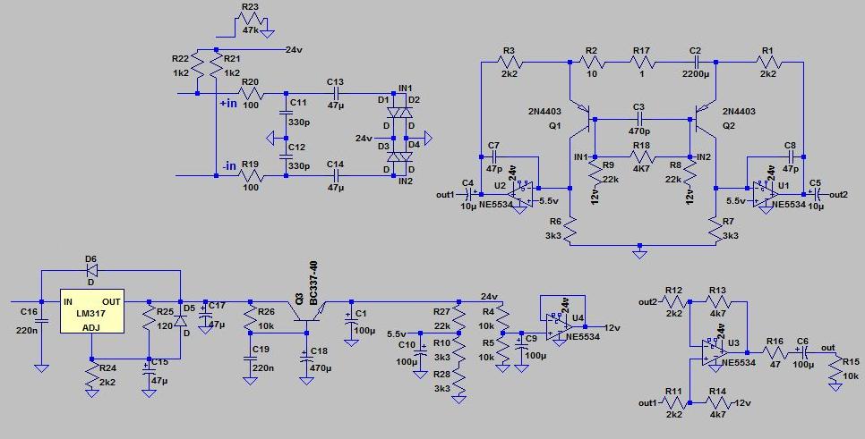
Wrt cap multiplier: while the output impedance is less defined, there are a few advantages in having it after the lm317. I can use one per channel and a single lm317 for a pair of channels. That also means I can make it small and use bc547c or the like as pass transistor (plenty of bc337-40 on hand). The high beta allows for a limited voltage drop while having decent filtering. Marginal cost is so low there's little reason not to add it.
Wrt the resistors strings: fixed. Made a string for each voltage reference because it made for easier pcb layout. Reduced the caps to 100uf.
Wrt input current: I cut the pear in 2 by dropping the ref voltage a bit to 5.5v and raising r6-r7 to 3.3k. It's now at 1.7ma as suggested.
Wrt "weakest link" : my willingness to use a single rail supply ? It raises complexity (virtual ground...) but it's a constraint I've to live with. The use of too many electrolytic caps in the signal path ? Hard to get around... The input transistors ? Iirc, Reichelt stocks the 2sa1085 @1.15€ a piece (assuming they're not fake). Worth it in this context ?
Attachments

- Status
- Not open for further replies.
- Home
- Amplifiers
- Solid State
- Mic preamp for dynamic mics, any glaring errors ?