Hello guys,
I was wondering if any genius out there who knows about preamp circuit who can explain this one to me.
See I am just getting into audio systems design and I am try to understand this preamp circuit and how it works.
A few questions:
1)what does the two cap in series does and why are they connect to ground?
2) what does R3, R1 and R2 does?
3) What is the uses of the polarity Reverse?
I have been reading up on these component but i am a little slow on understanding.
I would appreciate the help.
Attachments
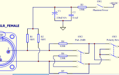
1) The two caps in series are bypass capacitors to filter the phantom power line; that is to remove any interference (the 0.1uF) capacitor and to remove any ripple (small voltage fluctuations that can upset sensitive equipment) using the 220uF capacitor. The capacitor acts as a low resistance path to ground for AC signals but lets smooth DC through.
2) R1 and R2 are to make sure that the power going to the XLR connector through to the mic is balanced and that there is the same voltage on each line. These also limit the current that a mic can draw from the phantom power (less than 10mA per mic). R3 will be to drop the voltage coming in to the power supply.
3) The polarity reverse switch changes over the two balanced signals (one is a mirror of the other) before the input to the preamp-sometimes these switches are called phase reverse switches.
thanks Jack that's very useful.
Do you know if the value of the capacitor is important? is there a reason why the capacitor are two different types?
Don't R3 and C2 make a high passs filter?
Do you know if the value of the capacitor is important? is there a reason why the capacitor are two different types?
Don't R3 and C2 make a high passs filter?
C1 and C2 are in parallel, not series. They form a low pass filter with R3, to remove noise from the phantom power supply. The ground connection is necessary for the filter to work. R3 is too small to give very much voltage drop. C1 covers audio frequencies. C2 ensures that the filter works at higher frequencies too, such as low RF.
The value of the capacitors is not too important, in the sense that the circuit would still work OK if they were half or double their value. This is often the case, but not always.
The value of the capacitors is not too important, in the sense that the circuit would still work OK if they were half or double their value. This is often the case, but not always.
Thanks for that DF96. This don't know if there is a reason for the two capacitor being two different type? and what if I remove C1, would that make much difference?
Sorry if am being irritating, just like to understand everything.
Sorry if am being irritating, just like to understand everything.
Other simple questions for u guys, which I would greatly appreciate. What is the purpose of the polarity reverse?
Sorry about my mistake.C1 and C2 are in parallel, not series.
I am still in the process of learning myself so whilst I did have a go at answering the question, I didn't quite get it right. Still though-it's part of the learning process 🙂.
Removing C1 would let audio noise through to the phantom supply. Not a good idea!
Reversing polarity means that the audio signal is inverted. This allows multi-mike setups to be properly phased. I don't know if there is a standard for mike signal polarity, but even if there is someone will violate it through carelessness or ignorance.
Reversing polarity means that the audio signal is inverted. This allows multi-mike setups to be properly phased. I don't know if there is a standard for mike signal polarity, but even if there is someone will violate it through carelessness or ignorance.
Good question!... a reason for the two capacitor being two different type? and what if I remove C1, would that make much difference?
Electrolytic capacitors are cheap and easily available in large values up to thousands of uF, but they don't work well at very high frequencies. Ceramic and plastic film capacitors are much better at high frequencies, but are not available in values higher than about 1 to 10 uF. At very high frequencies, especially radio frequencies, small physical size is important, so little ceramic caps are often the best.
In this circuit, C1 filters out audible noise like mains buzz, while C2 filters out radio frequency interference. If we could buy perfect capacitors, one big one would do both jobs.
C1 and C2 are only cleaning up noise and interference coming from the 48V power supply though, so their importance depends on the supply. For example, switch-mode power supplies generate a lot of radio frequency garbage while normal mains power supplies produce audible buzzing, and batteries are nice and quiet.
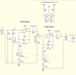
Radio frequency interference coming in through the microphone cable is not reduced by these capacitors. Presumably there's a filter somewhere else in the circuit to deal with that.
thanks guys, all of you have been of great help, now i have a better understanding of the phantom power circuit. 🙂
@godfrey, yeah i think there is a filter at the gain stage in the circuit, not too sure so i attached it for u to take a look. what do you think?
@godfrey, yeah i think there is a filter at the gain stage in the circuit, not too sure so i attached it for u to take a look. what do you think?
Attachments
- Status
- Not open for further replies.
- Home
- Amplifiers
- Solid State
- Mic Preamp circuit