I've posted this in my measurements thread, but thought I'd post it here as well 🙂
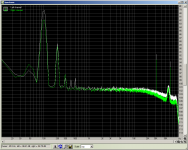
comparison between the 100Hz ripple (and harmonics) on the output of the reg with 1000uf 3r3 1000uF 3r3 1000uF pre reg, and a single 1000uF cap pre reg.
Measurement taken with 10X gain before being fed into and recorded on the pc's sound card using audacity.
Tony.
comparison between the 100Hz ripple (and harmonics) on the output of the reg with 1000uf 3r3 1000uF 3r3 1000uF pre reg, and a single 1000uF cap pre reg.
Measurement taken with 10X gain before being fed into and recorded on the pc's sound card using audacity.
Tony.
Attachments

Tony, which curve is which? And dB relative to what? By "pre reg," do you mean you put the caps ahead of the regulator?
Hi Sy, I would have thought which was which was obvious 😉 Left is with the CRCRC
by pre reg I mean the filter caps after the rectifier.
The recoding is any non-dc component residual on the power rails . For a relative to what, have a look at the following graph. It is a comparison of the output of the reg, compared to the preamp feeding the sound card with the probe shorted (left channel is the basic noise floor of the sound card + external 10X preamp ) and right is the measurement of noise on the output of the reg. Note that this one probably had 1000uF 3r3 4700uF 3r3 4700uF
for more info see my thread http://www.diyaudio.com/forums/power-supplies/188975-lm317-experiments-measurements.html which I started because I was hijacking someone elses 😉 BTW this is Georges technique I didn't come up with it 🙂
Tony.
Attachments

OK, prefiltering dropped the hum for sure. Now, what happens if you move one of those 1000uF caps to the adjust pin?
I will give it a try, but if you care to come over to my other thread I think you will see that with my circuit (implementation of Fred Dieckmann's suggestion) it won't make a hell of a lot of difference (I could be wrong). I'll also get out the scope set up the sound card to deliver a 10mv p2p sine wave and measure that on the 10X setting on the preamp so we have an absolute reference too 🙂 that has been bugging me a bit I don't know for sure that the sound card is running with no gain.
I can also change back to standard config of the reg, in which case I expect the big cap on the adj pin should make more of a difference.
But seriously I don't want to start hijacking another thread, we should discuss over in my LM317 experiments and measurements thread 🙂
Tony.
I can also change back to standard config of the reg, in which case I expect the big cap on the adj pin should make more of a difference.
But seriously I don't want to start hijacking another thread, we should discuss over in my LM317 experiments and measurements thread 🙂
Tony.
Feel free to keep posting or cross posting here. It is not a hijack as this discussion directly pertains too and seeks to answer many or the questions I had, have, and have yet to realize. Also, I suspect any discussion here may remain a bit less advanced, something helpful for me.
I'm looking forward to seeing your results from Sy's suggestion of 1000uF adj pin cap without the Dieckmann part.
I don't fully understand how to interpret your results to my application. Questions like "how does this apply in real world" and "how much noise will affect my recording" I am very curious about. At what point does a little noise not really matter since any mic will have it's own noise floor, etc? For example, I see the last image has the highest noise level at ~ 75dB but most is below 95dB. Does that mean this power supply would add that much noise to mic preamp? This are also with a 10x gain, so 20dB strong on your test than in actuality?
Thanks, and please keep it coming🙂!
It will add that much noise minus the power supply rejection of your preamp at that frequency. For example, if your preamp has 60dB of PSR at 1kHz and the supply has 2mV of noise at that frequency, the contribution to preamp noise will be 60dB down from 2mV, or 2uV. That's usually specified as input referenced, so for a 40dB gain preamp, the noise at the output due to power supply noise will be 40dB greater, or 0.2mV.
The phantom power is much more critical since that noise is injected into the input (that's why I recommended some RC sections following the reg).
The phantom power is much more critical since that noise is injected into the input (that's why I recommended some RC sections following the reg).
Shouldn"t any noise from the Phantom Power Supply be Common mode and rejected at the preamp ??
I don"t use a scope just my ears but I haven"t had any noise issues with Phantom power supplies ......
I don"t use a scope just my ears but I haven"t had any noise issues with Phantom power supplies ......
Thanks Sy.
I'll be honest, I still have a hard time relating to sound in terms of volts. I know that is exactly all it is, but it's a new language for me. I appreciate you replying in both volts and decibels. Helps me relate.
So, is it right to say (do I understand you) that if noise in wintermute's graph is at -95dB on his graph, after a 10x gain, then it is at -115 unamplified? If that is correct, and if the amp rejects 60dB, then the noise before amplification by the amp itself is at -175dB? If the amp is 60dB, then noise in the output of the amp has -115dB of noise from the powersupply?
Wintermute, when you say 3r3 resistors, is that 3.3 ohms or 33 ohms, and what type o resistor?
Minion, I'm really curious about your experiences recording with these powersupplies and the INA217 amps. Expect a PM from me.
As for phantom noise, I'm sure it's not the type of circuit discussed here, but you should hear the noise on my tascam interfac is turned on.
As for phantom noise, I'm sure it's not the type of circuit discussed here, but you should hear the noise on my tascam interfac is turned on.
So, is it right to say (do I understand you) that if noise in wintermute's graph is at -95dB on his graph, after a 10x gain, then it is at -115 unamplified? If that is correct, and if the amp rejects 60dB, then the noise before amplification by the amp itself is at -175dB? If the amp is 60dB, then noise in the output of the amp has -115dB of noise from the powersupply?
Well, let's work through it. It may take a few steps, but it's not really mysterious. Now first, understand that the total noise voltage is an integration of the noise floor over frequency- that's what a meter reads. But noise at different frequencies has different audibility. So when we're talking about dB in this context, we're pretty much talking about noise voltage densities at given frequencies. The noise voltage density is about the noise voltage contained in a frequency interval divided by the width of the interval. If the noise is flat and unweighted, it's straightforward to interconvert between the two ways of looking at the problem.
For simplicity, let's assume that at 1kHz, where your ear is sensitive, Tony's graph reads -95dB relative to 1V (that may not be right, he needs to specify that for you to use his results quantitatively, but 1V will do for the purpose of illustration). That means the noise input to the 10x interface (assuming its noise is low compared to the regulator) is -115dBV at that frequency.
Now, what's the reference level for your preamp's output? 500mV? OK, let's call it that, -6dBV. That corresponds to an input 60dB below that, -66dBV. Let's note that number on our palm.
OK, you have an amp with 60dB of PSR at 1kHz. We could take a shortcut by noting that the gain and PSR are the same, but for pedagogical purposes, let's not. The PSR is usually referred to the input. The power supply noise is -115dBV, the rejection takes you to -175dBV equivalent at the input. 60dB of gain, and you're at -115dBV. Nominal output is -6dBV, so the noise from the power supply at that frequency is -109dB below nominal output. Quiet enough! Now, recalculate it for the components at ripple frequency and you'll get a sense of whether or not extensive prefiltering is worth it. Grounding and layout will count at least as much here.
If you plug in the PSR of the 60dB mike amp I have in front of me (better than -120dB), the power supply requirements are pretty easy.
Thanks for the explanation SY! It's going to take me a little while to digest it. It was something that I hadn't yet come to grips with. I had relative differences, but whether or not they were of consequence I didn't know, however I was taking the approach that less was better and if not too extreme then why not do it 😉
ddietz, yes 3r3 is 3.3 Ohms (the r is a representation of the decimal point) I went with complete overkill on the power spec (7W) but the main reason for that was so they didn't generate much heat. With a load of around 360mA they get slightly warm. They are this type --> http://www.farnell.com/datasheets/90778.pdf nothing particularly special. Edit: Note that the value needs to be considered with respect to your current draw. Voltage drop goes up as current goes up, so it is a balancing act to ensure you don't drop the pre-reg voltage too much. Keeping a margin of 5V in to out is advisable (something I've yet to test in my setup) based on the sims I did, not sure yet real world as my voltage is a bit high due to a stuff up with my va calcs for my transformer (basically twice the rating it needed to be, sigh.) I can probably up the resistance to 6r6 to drop my voltage some more.
I'll see if I can do some more tests tonight with the large adjust pin cap, to be fair the comparisons I did before were when I'd already all but eliminated the ripple with pre-filtering, so it will be interesting to see the effect (both with and without the Dieckmann mod) when running a single 1000uF cap after the rectifier (which as seen in the previous post shows quite a bit higher than with the CRCRC).
This post http://www.diyaudio.com/forums/power-supplies/188975-lm317-experiments-measurements.html#post2573524 shows what I previously did with respect to comparisons between the std and modified circuit, and also with respect to 4.7uF adj cap and 11uF adj cap. From memory 10uF is what is suggested in the datasheet, I hadn't considered trying a much larger cap.
Tony.
Last edited:
When I was still new on the forum, Fred demanded that I tell him how I would design a good power supply. My response was, "For what?" which enraged him (Fred is easily outraged). But it's true- different circuits have different requirements before the supply is "good enough." A supply isn't "good" or "bad" absent context.
Now, it's fun in and of it's own right to try to learn by building the lowest noise/lowest impedance/highest precision supply you can. But really, at a certain point, it's not about making a circuit sound better, it's about the design challenge.😀
Now, it's fun in and of it's own right to try to learn by building the lowest noise/lowest impedance/highest precision supply you can. But really, at a certain point, it's not about making a circuit sound better, it's about the design challenge.😀
Now, it's fun in and of it's own right to try to learn by building the lowest noise/lowest impedance/highest precision supply you can. But really, at a certain point, it's not about making a circuit sound better, it's about the design challenge.😀
Absolutely 100% agree, the chances I will be able to audibly detect any differences are truly remote (unless it is very poor to begin with). This was certainly all about the learning and design challenge, and my never ending quest to ring the most amount of performance out of something that I can 🙂
Tony.
OK well it looks like I'm only going to get one measurement done tonight (the easiest one) so I'll post it now.
This is with the dieckmann mod (as I didn't have to reconfigure to do the measurement) and as I expected the bigger cap doesn't make a whole lot of difference. It does improve things, especially on the third fourth and fifth harmonics, but overall, at least with this circuit the CRCRC is much better value.
So what do we have:
1st pic single 1000uF elna silmic II as the filter capacitor.
left channel 4.7uF polyester bypass cap
right channel 1000uF elna silmic II bypass cap.
2nd pic shows the difference between a 1000uF cap (left) and 10,000uF cap (right) as the filter cap. adj pin was 4.7uF So brute force on the single filter cap does make a difference 🙂
Tony.
Attachments

Last edited:
Thanks for the information guys. Especially thank you to Sy for that walk though. Very helpful and well written. I'm short on time this morning so I can't go over these posts like I want, but thanks!
One question I do have relates to the Ina217 I plan to use, which has PSR at 1Kh of about 110dB. I'm not sure the nominal output of the device though. You spoke of preamp with 500mV. The spec sheet lists output as + and - 1.8V. How does that translate?
I'll try those calculations based on Winter's graphs later. But, at what point is noise audible. Say, how many dB down from nominal is noticeable?
Thanks!
Nominal output will depend on the sensitivity of your mike and/or the sensitivity of the line input that your preamp will be plugged into.
Nominal output will depend on the sensitivity of your mike and/or the sensitivity of the line input that your preamp will be plugged into.
How do I figure that out?
Basically what I am after is what you eluded to in your post, seven above this one. You said -109dB was quiet enough. I don't get how a 500mV preamp output equals -6dBV. Sorry, tried searching and couldn't find the right key words. I realize I won't know 'till I try it, but I'm trying to determine a sensible component starting point. Should I use CRCRC with really big caps after the rectifier, 1000uF on the adj pin, and large output caps. Will I be able to even tell the difference between that and a supply with only 1000uF pre-regulator, 100uF on the adj pin, and 1000uF post regulator. These are somewhat rhetorical questions, but I'll listen to opinions on their answers.
At what point does the difference become a non-issue in my "recording space" with a 20yr old Sm57 and a mid-grade AKG condensor? Its not so much that I want to cut corners but I do need to be efficient and economical. I don't want to build three PSUs if the first two are not good enough, at the same time I don't want to spend $50 and twice the case size if half that will be more than sufficient😉
Thanks again to everyone for the discussion, I'm learning a lot!
In case the definition isn't clear, "dBV" means "dB relative to 1V." So 500mV is -6dBV.
Let me use my mike and mike preamp as an example. My mike outputs about 0.5mV for a 94dB SPL (it's a ribbon, not very sensitive). If the loudest sound I'm going to capture is 114dB SPL at the mike, that's 20dB above 0.5mV = 5mV. My preamp has 60dB of gain, which translates that to 5V. That's also the maximum input to the line in of my ADC, so I use 5V as my reference "nominal" level.
Here's a nice calculator which will let you translate from your mike's sensitivity spec to voltages:
http://www.sengpielaudio.com/calculator-transferfactor.htm
edit: Just to take things further, if my preamp has a signal to noise (referred to 5V) of -100dB, then the equivalent noise contribution of the preamp in a recording is 114 -100 = 14dB SPL. That's quieter than nearly any studio.
Thanks again to all for the replies. Sy, I'll need to look that over later as I still don't get how to know that 0.5mV is -6dBV.
Anyway, I got my regulators yesterday so I breadboarded a simple supy using two 18vac smps wall warts and small filter caps. This brings up a couple new questions for me
First, the voltage with out a load was 20vdc, but 15vdc with even a small load. I have the regulator set for 15vdc. As 20 is above the preamp chips max voltage rating, will inhale a voltage spike when it turns on or is the load instantly seen? Do I need an output resistor as a dummy load always? I also suspect the smps are part of the higher voltage when not loaded, is that right? If so, will a quality torroid have the same problem?
Second, one rail is about 0.2Vdc higher than the other regardless of load. The adj resistors are not matched now as I only had two of each necessary value. I'm waiting for a mouser order to arrive with more parts. Will a voltage difference cause a problem, if yes how big a difference is an issue? Will well matched resistors solve the problem or do I need to use trimmer resistors instead?
Thanks all again!!!
- Status
- Not open for further replies.
- Home
- Amplifiers
- Power Supplies
- Mic pre and phantom power PSU questions