Eva said:What I would like to see is the carrier residual with no input signal and 10A DC load to one of the supply rails... 😉
i have no interesting to answer your new questiong before you Proof that you can make a 10x better 100k class-d amp better than MCD. (this is what you had told others here )
make it and show it , please 🙂
action is quite better than any words
rg
fumac
mahirerensan said:yes please🙂
sorry forget your asking
too busy , bucase doing hifi show at shanghai .
ok here is the picture what you need
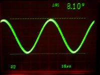
the picture is 1k at 8vpp output at 4ohm of mcd-255
sorry for the Jitter from my hand, but you can get the idel voltage of the 1mhz pwm
Attachments
ChocoHolic said:
Bad girl !
You really want to trigger everything that can ring...
😉
hello Choco longtime no see
how about you after back home
rg
fumac
fumac said:
the picture is 1k at 8vpp output at 4ohm of mcd-255
sorry for the Jitter from my hand, but you can get the idel voltage of the 1mhz pwm
The jitter on the sinewave is not from your hand. That's why you don't want us to see carrier residual under load 😉
Eva said:
The jitter on the sinewave is not from your hand. That's why you don't want us to see carrier residual under load 😉
🙂 hahahah
ok, i will post a no hand jitter picture, so funny girl.
rg
fumac
fumac said:
hello Choco longtime no see
how about you after back home
rg
fumac
Hi Fumac,
...it is ..so so... to busy & no time for class D fun...
I think Eva is asking for something different from what you posted.
She is interested in the HF output that you see if you run your amp with zero input.
You typically see a sine wave of the carrier frequency and some peaks at the switching moments.
This peaks are causing EMI issues.
These peaks become worse in hard switching conditions, which occur at higher output power.
But at high power the peaks are difficult to see on the scope, so it is helpful to run with zero input signal and simulate an output current be simply putting a resistor between output and positive rail, or output and negative rail. You do not need to go for 10A, already currents of 3A do usually show most of the hard switching headache.
Hi, EVA, Choco,
Do you have example of such a test, scope capture of good and bad example? Interesting test.
Do you have example of such a test, scope capture of good and bad example? Interesting test.
I have a screen shot of this test without added DC load.
So it is not the worst situation. This were results, which I reached with my bread board. I hope to get it better with a reasonable layout. But already on the bread board the HF "blibs" were acceptable and by far less than the carrier. See posting 46.
http://www.diyaudio.com/forums/showthread.php?s=&threadid=101774&perpage=25&pagenumber=2
Bruno is giving good & bad examples here:
http://www.hypex.nl/applications/emi.htm
But take care - he still has not corrected a typo in the time base. Correct time base for his screen shots is 500ns/grid.
But at high power the peaks are difficult to see on the scope, so it is helpful to run with zero input signal and simulate an output current be simply putting a resistor between output and positive rail, or output and negative rail. You do not need to go for 10A, already currents of 3A do usually show most of the hard switching headache.
Take care about what PSU that you use for that test ! 😉
regards
Charles
Why?phase_accurate said:Take care about what PSU that you use for that test ! 😉
Evil answer: Try it and you'll see !!! 


Nice answer: Because of supply pumping effect !

Regards
Charles
Nice answer: Because of supply pumping effect !
Regards
Charles
Evil answer: think it over!
Nice answer: in this case supply pumping is cancelled by load current, because load current flows from the pumped side of the supply. +10 A load current causes 5 A pumping in negative side, but the 10 A goes thru the load, and landed on negative side, so effective supply current is 5 A in normal direction on both side.
Nice answer: in this case supply pumping is cancelled by load current, because load current flows from the pumped side of the supply. +10 A load current causes 5 A pumping in negative side, but the 10 A goes thru the load, and landed on negative side, so effective supply current is 5 A in normal direction on both side.
Not bridged.
Try it, and you'll see! 😀
Think! There is no load connected to GND. How could supply currents be different? This way the amp is a basic step-down converter.
Try it, and you'll see! 😀
Think! There is no load connected to GND. How could supply currents be different? This way the amp is a basic step-down converter.
Ahhhhh !!! I didn't get that they want to connect the load between output and supply rail. In this case of course it doesn't matter.
Regards
Charles
Regards
Charles
- Status
- Not open for further replies.
- Home
- Amplifiers
- Class D
- MHz amplifier