In this first post I will update all important stuff continuously for your convenience
New input interface for ACH-01 and stiffer
carbon fiber support (28 may) post 66 (better!!)
Add stiffnes post 69 (better)
Add "dust cap" stiffener... is it better?? Post 71
Background: After have been experimenting a lot with Servo subwoofers or MFB motional feedback in the 90-ties with success I went to dipole subwoofers and QUAD ESL 63 electrostatics (modified). Everything was fine until I realized that sometimes the ESL 63 playing on their own, had a magic in upper bass that can not be achieved with dynamic woofers... nope nix njet nej ikke.
8-10% distortion in a woofer does not blend well with QUAD or other electrostatics with <1% distortion in bass.
So only way out is to reduce distortion with a factor of TEN ! (Or go back to dynamic speakers..😱 naa.. )
And here is how it is done 😎
Circuit: First I am using ACH-01 accelerometer and using Piratelogic Electronics EVE 2020 circuit boards which is wery convenient, however this circuit is not designed directly to fit ACH-01 so some tweaking on some values has to be done... also using CFB is changing frequency responce and phase a lot and on top of that dipole woofer, the frequency correction and phase response will be TOTALLY different from using the EVE 2020 the "normal way"
Which is to drive voltage amplifiers with Starbass accelerometers and small woofers in small boxes. If you want to do so there is another thread by chriscam on this forum.
So be careful, the manual for using EVE 2020 will not guide you the right way for this combination... but nice and easy.
We will get it working! And if you want to make it more easy use Star bass accelerometer. They seems to work great.
The benefits with MFB CFB and Dipoles: Using motional feedback to a Dipole woofer system is double or maybe triple compared to a closed box!
First: Distortion comes with longer strokes, which you have a lot more with dipoles than any other principle.
Second: Since the dipole compensation 6dB/octave raise the low fundamental tones, those fundamental tones has corresponding harmonics which will be raised several dB! If you play a 100Hz tone, the 2nd harmonic of this tone is also lifted 6dB, and worse... the 9th harmonic 900Hz will be lifted >18dB!!
Third: The 9th harmonic 900Hz is much more disturbing and noticeable since your ears are much more sensitive in those frequencies.
Dipole woofers are hard to integrate with low distortion midbass of an electrostatic speaker!
Reed the theory papers below and in nr 3, you find the benefits of combining CFB and MFB.
Distortion reduction and measurements part 1: Post 30 shows 2-3 times lower distortion, but it will be improved!
I have reached a more than ten fold reduction in distortion or 22dB in a prototype, and here i will guide you trough the building, schematics, measurements setup and all problems that you may face during the journey, I know, I have done all mistakes there is, and will try to cover them all.
SERVO subwoofers or MFB theory:
1. http://rmsacoustics.nl/papers/whitepaperMFBtheory.pdf
2. http://rmsacoustics.nl/papers/whitepaperMFBdesign.pdf
3. https://www.rmsacoustics.nl/papers/Impulse Compensated Driver setup.pdf
Input stage: The black and white part of the schematic is the accelerometer itself and the buffer J310 68k and 820 ohm resistors, mounted on the woofer, these are SMD components glued to the cone and hard wired under a microscope... crazy idea from the beginning, and even more stupid when the J310 was fried :-(
A part of the schematic EVE 2020.0 is shown, and a table with some assumptions. With ACH-01 you should add an impedance buffer see below.. (Starbass has a buffer already built in)
Updated 220511
Accelerometer gain stage and loop mixer: Post 4 is misleading regarding J310 FET.. see picture below.
I have seen the application note schematic for ACH 01, but was mislead by another users design.
The ACH 01 shall have a negative bias as shown on the application note, to minimize distortion.
I will do a last try with ACH-01 Otherwise I buy ClingOn from Chris, and just get it working...
Big thanks to Robert-H Munnig Schmidt at RMS acoustics for explanation!! 🏆
Rob has achieved 30dB loop gain and 45deg phase margin... is that a world record? (some people is impressed by Messi and Ronaldo....)
Stability, Phase margin, and OLTF measurements: Post 34
Stability at low frequency is achieved but at around 3kHz it looks really messy. So I am reaching out for any help, here.
Below is the input side of the accelerometer on EVE 2020 board. From here you will see that everything has to be made different with Dipoles.

How it should look like!

I did a last try with ACH-01, with stiffer carbon fiber support and new electric interface in post 66 and it works much better!
New input interface for ACH-01 and stiffer
carbon fiber support (28 may) post 66 (better!!)
Add stiffnes post 69 (better)
Add "dust cap" stiffener... is it better?? Post 71
Background: After have been experimenting a lot with Servo subwoofers or MFB motional feedback in the 90-ties with success I went to dipole subwoofers and QUAD ESL 63 electrostatics (modified). Everything was fine until I realized that sometimes the ESL 63 playing on their own, had a magic in upper bass that can not be achieved with dynamic woofers... nope nix njet nej ikke.
8-10% distortion in a woofer does not blend well with QUAD or other electrostatics with <1% distortion in bass.
So only way out is to reduce distortion with a factor of TEN ! (Or go back to dynamic speakers..😱 naa.. )
And here is how it is done 😎
Circuit: First I am using ACH-01 accelerometer and using Piratelogic Electronics EVE 2020 circuit boards which is wery convenient, however this circuit is not designed directly to fit ACH-01 so some tweaking on some values has to be done... also using CFB is changing frequency responce and phase a lot and on top of that dipole woofer, the frequency correction and phase response will be TOTALLY different from using the EVE 2020 the "normal way"
Which is to drive voltage amplifiers with Starbass accelerometers and small woofers in small boxes. If you want to do so there is another thread by chriscam on this forum.
So be careful, the manual for using EVE 2020 will not guide you the right way for this combination... but nice and easy.
We will get it working! And if you want to make it more easy use Star bass accelerometer. They seems to work great.
The benefits with MFB CFB and Dipoles: Using motional feedback to a Dipole woofer system is double or maybe triple compared to a closed box!
First: Distortion comes with longer strokes, which you have a lot more with dipoles than any other principle.
Second: Since the dipole compensation 6dB/octave raise the low fundamental tones, those fundamental tones has corresponding harmonics which will be raised several dB! If you play a 100Hz tone, the 2nd harmonic of this tone is also lifted 6dB, and worse... the 9th harmonic 900Hz will be lifted >18dB!!
Third: The 9th harmonic 900Hz is much more disturbing and noticeable since your ears are much more sensitive in those frequencies.
Dipole woofers are hard to integrate with low distortion midbass of an electrostatic speaker!
Reed the theory papers below and in nr 3, you find the benefits of combining CFB and MFB.
Distortion reduction and measurements part 1: Post 30 shows 2-3 times lower distortion, but it will be improved!
I have reached a more than ten fold reduction in distortion or 22dB in a prototype, and here i will guide you trough the building, schematics, measurements setup and all problems that you may face during the journey, I know, I have done all mistakes there is, and will try to cover them all.
SERVO subwoofers or MFB theory:
1. http://rmsacoustics.nl/papers/whitepaperMFBtheory.pdf
2. http://rmsacoustics.nl/papers/whitepaperMFBdesign.pdf
3. https://www.rmsacoustics.nl/papers/Impulse Compensated Driver setup.pdf
Input stage: The black and white part of the schematic is the accelerometer itself and the buffer J310 68k and 820 ohm resistors, mounted on the woofer, these are SMD components glued to the cone and hard wired under a microscope... crazy idea from the beginning, and even more stupid when the J310 was fried :-(
A part of the schematic EVE 2020.0 is shown, and a table with some assumptions. With ACH-01 you should add an impedance buffer see below.. (Starbass has a buffer already built in)
Updated 220511
Accelerometer gain stage and loop mixer: Post 4 is misleading regarding J310 FET.. see picture below.
I have seen the application note schematic for ACH 01, but was mislead by another users design.
The ACH 01 shall have a negative bias as shown on the application note, to minimize distortion.
I will do a last try with ACH-01 Otherwise I buy ClingOn from Chris, and just get it working...
Big thanks to Robert-H Munnig Schmidt at RMS acoustics for explanation!! 🏆
Rob has achieved 30dB loop gain and 45deg phase margin... is that a world record? (some people is impressed by Messi and Ronaldo....)
Stability, Phase margin, and OLTF measurements: Post 34
Stability at low frequency is achieved but at around 3kHz it looks really messy. So I am reaching out for any help, here.
Below is the input side of the accelerometer on EVE 2020 board. From here you will see that everything has to be made different with Dipoles.
How it should look like!
I did a last try with ACH-01, with stiffer carbon fiber support and new electric interface in post 66 and it works much better!
Attachments
Last edited:
I tried to follow this document by the way:
https://uweb.engr.arizona.edu/~brew/ece304spr07/Pdf/PNP current Mirror.pdf
https://uweb.engr.arizona.edu/~brew/ece304spr07/Pdf/PNP current Mirror.pdf
What is the target/purpose of the extra J310 stage? Is the bias for the ACH-01 too low in the original set up?
Since it is a Dipole project and i have no need to do frequency extension (fs in free air is 20 Hz and i will only use the dipole between 27Hz-120Hz) my only goal is to reduce distortion. And in Dipoles there is a lot of excursion=distortion at low frequencies.
This is why i want to optimize the feedback circuit (working point of J310 and the current mirror) to achieve as low distortion as possible.
Next thing is to keep the bandwidth of the servo loop high enough to reduce the harmonics up to.. lets say 9th. -> 9*120 Hz is 1080Hz and that gives a C12 of 15nF and C16/R28 tuned to 1kHz as well.
My Dayton IB woofers has a nasty breakup at 1100kHz but this frequency will not be played, I use 24dB filter at 120Hz = attenuation of >72dB at 1100Hz.
Any thoughts or comments?
I have seen others using this particular stage, probably for lowering output impedance. I have not tried without it.What is the target/purpose of the extra J310 stage? Is the bias for the ACH-01 too low in the original set up?
I have seen others using this particular stage,
Could you share the circuits (or their source) of the these "others"?
First post has some errors in Resistor values. This is how it is.
Current mirror is not symmetrical and the current trough R11 and R12 is not the same.
2.52mA in R11 and 1.06 mA in R12.
2.72mA in R8 and 4.17mA in R9... BCV62 is BAD.
6.28mA in R17 and 0.991mA in R6
5.6 volts to J310 and it takes 4.17mA, i can not reach the "R3" 820ohm source resistor on J310
Well i guess i have to order BCV62s
Before I messed it up I reached 22dB reduction of distortion on a free air element. Quite amazing!
When I played the same level out without MFB I could clearly spot the location of the woofer playing low frequencies (around 20-25 Hz).
But with MFB connected I could only see the cone moving and lock on REW that the level was the same, but i could not hear it!
This tells me that if you can spot your sub in the room playing 20 Hz you are listening to distortion! I´m not saying that it is not good adding 2nd harmonics, but 3d and 5th harmonic is not very pleasant. And with this circuit you can do magic stuff. I had some problem trying to optimize the conditions for ACH-01. Today I would go for Starbass ClingOn from Pirate logic. Then I would have it playing since 2 years back. But I really liked the performance of ACH-01 I guess it´s still the most linear accelerometer on the market. ACH-01 is extremely sensitive to strain on it´s base, so you have to mount it on something that is not flexing. There is a thesis paper in the subject here page 47
https://repository.tudelft.nl/islandora/object/uuid:dbdc165b-31c9-477a-afc6-4093045c8479
I told you... starbass is easier 🙂
Thanks for not telling me i´m blind! (or stupid)
R12 is 10kohms originally?? How come by the way?
slightly more than a mA in the current mirror saturates BCV 62... it was not broken.
Changing R12 to 1k and everything settles on the new PCB version (EVE 2020.0)
I still have the question on optimizing the current mirror to get lowest possible distortion?

This is the open loop transfer function. I got it working but I only reach 10dB feedback With my new version? Need to reduce peak at 22Hz... and what is happening around 530Hz?
Maybe I am mistaken, but there is something strange in the measurement: from 20Hz to 10Hz it looks as if the slope is about 24db/Octave, yet the phase between 20 and 13 Hz only gradually rises. With a 4e order roll off, phase should reach + 180 degrees much sooner.
I made a very quick n dirty sim of your curve, that shows phase should rise much quicker to +180 degrees than in your picture. Its this the result of 2 channel measurement?

I made a very quick n dirty sim of your curve, that shows phase should rise much quicker to +180 degrees than in your picture. Its this the result of 2 channel measurement?
Thanks BODEN!
I made two acoustic measurements using timing reference by a high frequency chirp signal in REW. One with MFB feedback, and one without. The microphone is not moved in between! And with the mathemathical functions in REW I calculated OLTF. There could be a timing error in the measurements that is messing up everything...
I made two acoustic measurements using timing reference by a high frequency chirp signal in REW. One with MFB feedback, and one without. The microphone is not moved in between! And with the mathemathical functions in REW I calculated OLTF. There could be a timing error in the measurements that is messing up everything...
So this is an acoustic (NF?) measurement?
What you need in the first place is a measurement of the sensor output in your target application, i.e. in your dipoles. Ideally the sensor output should fully track the acoustic output between 5 and 500 Hz. Above that NF measurements are no longer valid with larger drivers.
The first stumbling stone is to obtain perfect tracking: the sensors are extremely sensitive to proper mounting, voicecoil vibrations and cone-breakups, that do not always show up in mic measurements. This is precisely where I am stuck myself at the moment, not having time to proceed for the next 3 months or so.
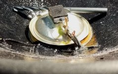
I have trouble getting enough signal from the accelerometer. So for trouble shooting i cranked up volume to max at 20 Hz and get 85mV RMS or 250mV pk-pk over R12. or 250uA pk-pk. That should give us 250*820 =205mV pk-pk over R3 (I can not reach that resistor or J310 FET since they are glued on the cone, see the red circle)
In post 9 you see that the ACH_01 is feeding J310, and the current mirror drives the signal over R12.
The sensitivity of ACH-01 is 9mV/G, i should have a lot lot more signal than this. Don´t you agree?
In theory, If we calculate that we reach x-max (14mm) of the woofer at 20 Hz, that is 22G.
a=W^2 * A -> a = (2*3.14*20)^2 * 0.014 and multiplied with 9mV/G and 196mV pk-pk over R3 (max acceleration) from ACH-01...
My feeling is that theory and measurement is quite close...

So i need to crank up the feedback a little bit more.
10dB or 8 times the voltage.
Please if you find error in my calculation just correct me. Thanks!
In post 9 you see that the ACH_01 is feeding J310, and the current mirror drives the signal over R12.
The sensitivity of ACH-01 is 9mV/G, i should have a lot lot more signal than this. Don´t you agree?
In theory, If we calculate that we reach x-max (14mm) of the woofer at 20 Hz, that is 22G.
a=W^2 * A -> a = (2*3.14*20)^2 * 0.014 and multiplied with 9mV/G and 196mV pk-pk over R3 (max acceleration) from ACH-01...
My feeling is that theory and measurement is quite close...
So i need to crank up the feedback a little bit more.
10dB or 8 times the voltage.
Please if you find error in my calculation just correct me. Thanks!
Maybe Chriscam could chime in here? I am not familiar enough with the dimensioning and functioning of the current mirror.
Here is the Open Loop Transfer Function OLTF measured electrically.
https://www.diyaudio.com/community/...s-using-piratelogic-electronics.336070/page-8
Post 147 from Bolserst show how it is working.

0 dB crossing shows that the feedback is quite limited (up to 60Hz, and maximum 9dB at 20Hz)
As you can see I need to crank the feedback up around 10dB extra.
Comments?
I also need to flatten the feedback loop by adding a RC link over R25 ( 47nF 27kOhm ) to flatten the curve. The question is will this increase or decrease my HF Phase margin? Help needed..
The strange frequency response is explained by my current feedback amplifier CFB, or mixed mode in reality (see the end of this post) . Which means that the frequency response without MFB will mimic the impedance curve! First the Impedance curve of the woofer:

And this is the acoustic frequency response without MFB, measured 15cm from the woofer (mounted in a H baffle, so some acoustic extra loading)

Do not trust the Phase since the timing is done in a loopback with almost zero delay, and microphone is approx 15 cm from cone.
The CFB amplifier mixed mode principle:

I added 7uH in series with the current sensing resistor for increased stability of the amplifier, since the inductance of the driver increases the gain a lot at higher frequencies it was really needed.
There is a question mark on a non existing resistor, if I decide to reduce the huge gain I have around 20 Hz I will put 33 Ohms here and work my way down in resistance. Thanks for feedback! Not only MFB or CFB but also diyAFB
https://www.diyaudio.com/community/...s-using-piratelogic-electronics.336070/page-8
Post 147 from Bolserst show how it is working.
0 dB crossing shows that the feedback is quite limited (up to 60Hz, and maximum 9dB at 20Hz)
As you can see I need to crank the feedback up around 10dB extra.
Comments?
I also need to flatten the feedback loop by adding a RC link over R25 ( 47nF 27kOhm ) to flatten the curve. The question is will this increase or decrease my HF Phase margin? Help needed..
The strange frequency response is explained by my current feedback amplifier CFB, or mixed mode in reality (see the end of this post) . Which means that the frequency response without MFB will mimic the impedance curve! First the Impedance curve of the woofer:
And this is the acoustic frequency response without MFB, measured 15cm from the woofer (mounted in a H baffle, so some acoustic extra loading)
Do not trust the Phase since the timing is done in a loopback with almost zero delay, and microphone is approx 15 cm from cone.
The CFB amplifier mixed mode principle:
I added 7uH in series with the current sensing resistor for increased stability of the amplifier, since the inductance of the driver increases the gain a lot at higher frequencies it was really needed.
There is a question mark on a non existing resistor, if I decide to reduce the huge gain I have around 20 Hz I will put 33 Ohms here and work my way down in resistance. Thanks for feedback! Not only MFB or CFB but also diyAFB
- Home
- Loudspeakers
- Subwoofers
- MFB and CFB using Piratelogics Electronic