Hi,
Can I run an op amp off the existing 10v rails on the mezmarise board. opa 1692 650 µA per Channel. Using the input relays to have a gain position on the input rotary, for each input. Thus accommodating the rare occasion my system requires more gain without permanently introducing another stage.
Wonderfully transparent pre amp with drive, Many thanks.
Any thoughts gratefully received,
Kind regards Nick.
Yes you can, it's a clean rail to tap from, only make sure no noise or oscillations will be introduced and shared. Check all is well in the full configuration with op-amp using a scope. AC coupled at 5mV vertical and 50uS horizontal will show. Looking for a thin clean DC line. Nice that you like the preamp, cheers.
leds
Hi
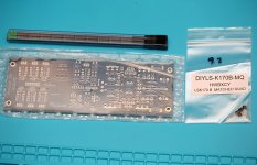
My Mezmerize DCB1 10 years after board has arrived from the site shop
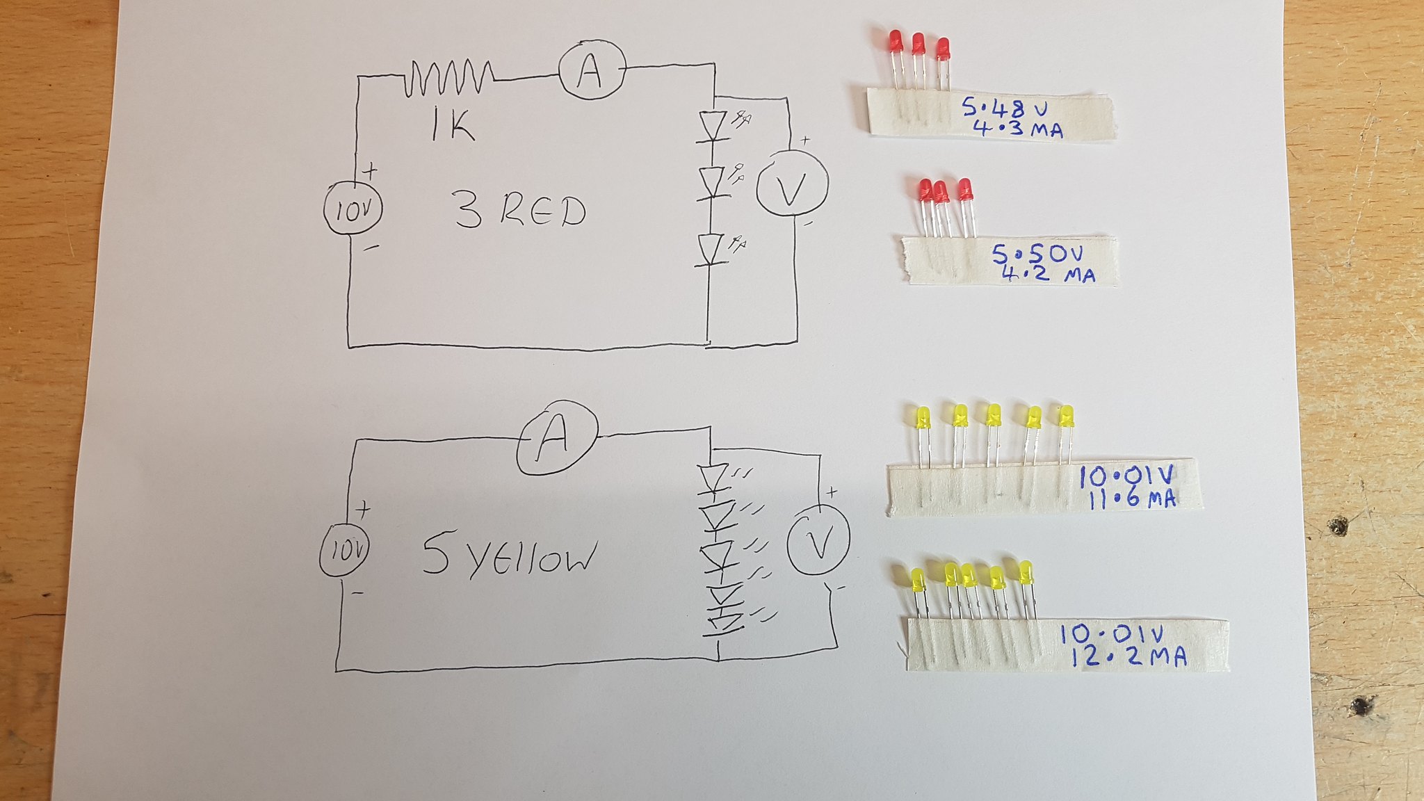
I have had trouble getting hold of the kingbright leds as discontinued i had a few leds in my parts bin this is what i have managed to get
3 x red leds tested with 10v and 1K resistor 5.50v 4.2ma
5.48v 4.3ma
5 yellow leds tested with 10v 10.01v 11.6ma
10.01v 12.2ma
is this ok or should i try to get a better 5.4v match ?
kind regards Glenn
 20190712_134613 by glenn jarrett, on Flickr
Hi
My Mezmerize DCB1 10 years after board has arrived from the site shop
I have had trouble getting hold of the kingbright leds as discontinued i had a few leds in my parts bin this is what i have managed to get
3 x red leds tested with 10v and 1K resistor 5.50v 4.2ma
5.48v 4.3ma
5 yellow leds tested with 10v 10.01v 11.6ma
10.01v 12.2ma
is this ok or should i try to get a better 5.4v match ?
kind regards Glenn
20190712_134613 by glenn jarrett, on FlickrYes you can use all of the above Leds or 10R set resistors without any significant deviations from intended biasing. Maybe expect somewhat higher than +/- 10V rails. There is the bias current for the quintets bringing them to total Vf, depends on their tail JFET's IDSS, plus one Vbe added in the circuit, coming from the error amplifier BJT. Inconsequential differences. By the way amber Kingbright Leds from the same series as the listed discontinued reds are adequate as well.
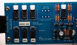
BCB-1 build coming on nicely
decided to go for the kingbright as the leds i had were from China via ebay with no info .
just waiting for the R set resistors to arrive and mount the 4x mosfets on the sinks .
Going to power up first check voltages then solder the 4 amp fets in which way round would you place the 4 fets ?
would 7.57 - 7.46 - 7.47 - 7.49 be ok ?
or 7.57 - 7.47 - 7.46 - 7.49
 20190719_122305 by glenn jarrett, on Flickr
decided to go for the kingbright as the leds i had were from China via ebay with no info .
just waiting for the R set resistors to arrive and mount the 4x mosfets on the sinks .
Going to power up first check voltages then solder the 4 amp fets in which way round would you place the 4 fets ?
would 7.57 - 7.46 - 7.47 - 7.49 be ok ?
or 7.57 - 7.47 - 7.46 - 7.49
20190719_122305 by glenn jarrett, on Flickr
Last edited:
7.57 - 7.49 - 7.46 - 7.47 is the better order
The first pair is going to naturally produce more DC offset but that's the nearest arrangement with what IDSS samples you got in hand
The first pair is going to naturally produce more DC offset but that's the nearest arrangement with what IDSS samples you got in hand
Have two B1s but getting on board with the Mez B1!
Hello All!
I have built and enjoyed two B1 units (one balanced) and now want to give the Mez B1 a go. Four questions:
1) I see the boards are still for sale but the SK170 sources seem sparse since the 10 years later board and BOM was issued. Suggestions for sources of well-matched sets for the signal path?
2) I want to build balanced (all the more need for good matching) so is it just a matter of doubling up all parts and the board except using a single tranny that has twice the specified current capacity?
3) I want to integrate a remote controlled relay based ladder type attenuator. See The δ1 relay-based R-2R stereo attenuator Other than space and power supply what other cautionary notes would you have for me?
4) What is the purpose of the 100 ohm resistor on second set of outputs? I intend to have multiple balanced outputs on my unit.
Thank you!
1) punkydawgs on eBay sells 8X matched which are verified and well near together but not cheap.
You could alternatively transplant JFETs from your older B1 builds if you still got them.
2) Doubling up all parts yes. Including two transformers or one with two completely separate sets of secondary wires. Because the PSU sections are independent on bridges and won't share a single AC source correctly.
3) The input to ground resistor of DCB1 (220k but flexible) should be at least 10x higher than the output impedance of the attenuator.
4) Breaking interaction between parallel connected equipment. You may measure significant extra THD on an output if with an idling component hooked directly in parallel. Depends on its input circuitry characteristics and the interconnects also.
I just saw in the store, Jason updated the IDSS matched Linear Systems JFETs offers
Linear Systems Matched JFETs – diyAudio Store
Linear Systems Matched JFETs – diyAudio Store
Thank you! On another matter, why do you recommend to put a 100ohm resistor in series with the hot for the second set of outputs on a preamp to avoid parasitic influences from one amp to the next when most amps already have a resistor at the input?
Because you never know how various parallel connected gear will interact. I have met the odd issue. Its good general practice to have the extra resistors unless willing and equipped to specifically test. Measure THD from the main DCB1 output with and without your other gear hooked up on its secondary parallel output. Without any resistors. If performance remains the same, don't put split out buffering resistors.

Attachments
Last edited:
Very nice. Did you run some music through it yet? Happy to see diyA's shop offers the crucial quad again.
I'm finally getting round to collecting all the parts to this but looking through the BOM there are two resistor values that don't match the board that I have, the 2x68r at the side of the reservoir caps and the 10r resistors, have the recommended values changed for these?
Thanks
Thanks
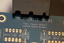
It has Mezmerize version by CRT printed on it, are there any circuit differences or is It just component value differences?
Last edited by a moderator:
- Home
- The diyAudio Store
- Mezmerize B1 Buffer Preamp