They run pretty warm. The bare To247 (or thereabouts) has an Rth j-a of about 50C/W
You should be able to identify this from the datasheet and from your dissipations calculate the junction temperatures.
You can also estimate the Ta inside you case by sticking a thermometer inside and letting it cook for a while.
You should be able to identify this from the datasheet and from your dissipations calculate the junction temperatures.
You can also estimate the Ta inside you case by sticking a thermometer inside and letting it cook for a while.
LED Issue
I have just finished my Mezmerise - in standard form and it works well. There is just one puzzling issue regarding the LEDs
The inner group come on soon after startup and then go off, only to return some minutes later on one side only.
The pictures attached give an idea, though of only phone quality.
Have I done something wrong? 😕
Attachments
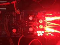
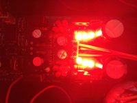
Some intermittent solder joint in those LEDS or in the K170 next to them maybe. Or an LED that had too much time under the iron when soldering was done and became erratic. They look like 5mm and bunched together, could be heating up themselves it would be another but less likely suspicion.
hi guys,
I finally got the time to do some measurements and would like to hear your opinion on the outcome.:
power supply
+10,7
-10,2
DC offset
2,5 mv
0,7 mv
Do these measurements fall within the recommended criteria?
I finally got the time to do some measurements and would like to hear your opinion on the outcome.:
power supply
+10,7
-10,2
DC offset
2,5 mv
0,7 mv
Do these measurements fall within the recommended criteria?
To those who are more knowledgable than I...
about the 6 unmatched k170 BL JFETS required for the mezmerize B1 buffer..
would J 111 N channel JFET switches function well as a replacement? I have some, but im wondering if i should acquire something else, before i solder them in.
Thanks
about the 6 unmatched k170 BL JFETS required for the mezmerize B1 buffer..
would J 111 N channel JFET switches function well as a replacement? I have some, but im wondering if i should acquire something else, before i solder them in.
Thanks
the 4 B1 devices need to be low noise high gm.
Of all the others only two need to be low Idss, high gm, low Vp devices (the two that operate with 0.6Vbe across them).
All the others can be any gm type.
That adds up to six 2sk170/lsk170/bf862 for a stereo build. (the bf862 would need an smd to to92 adaptor)
Of all the others only two need to be low Idss, high gm, low Vp devices (the two that operate with 0.6Vbe across them).
All the others can be any gm type.
That adds up to six 2sk170/lsk170/bf862 for a stereo build. (the bf862 would need an smd to to92 adaptor)
J111 can run high mA through itself, the error amplifier BJT, and the LEDS, compromising long term reliability. All FETS are used at IDSS in this circuit. If one must use some J series better use J112. Its not a different FET for noise and gm while the IDSS is moderate vs J111.
*Any gm any parasitic capacitance and any noise spec for the rest of FETS than those six can change the power supply performance to a degree nonetheless.
*Any gm any parasitic capacitance and any noise spec for the rest of FETS than those six can change the power supply performance to a degree nonetheless.
Does anyone know if there's a difference between the currently available blue mesmerize board and the older black colored version of the board?
If talking about the old single layer black board, yes there is difference. The output relay just disconnects the output signal. In the blue double layer board, the one the DIYA store always carried, the output relay mutes the output signal to ground instead.
This reads like the output signal is being connected to ground..................the output relay mutes the output signal to ground instead.
Is that what you meant it to say?
Or did you mean that the return route from the speaker to ground is opened by the relay?
or something else?
The output of the DCB1 is shorted to ground during power up delay or when off. Not the power amplifier's output. For very many older builds when the board was single layer the output relay was just disconnecting the output. Until one time someone with a very high impedance input power amplifier (maybe tube, don't remember) could pick up some buzz through his interconnects while the DCB1 was off or while delaying output for stability in power up. Don't know if the interconnects were unusually long or unshielded.
If there is interference around, open circuit to high impedance and not that great shielding in wiring can pick up things from the environment. Not an often thing, at least never reported before by DCB1 builders by then, and why having the amp on when the control buffer is off? Don't know maybe for warm up. So with the opportunity of double layer edition some top layer vias were added to short signals to ground when the relay was not engaged. Thus to address any chances.
If there is interference around, open circuit to high impedance and not that great shielding in wiring can pick up things from the environment. Not an often thing, at least never reported before by DCB1 builders by then, and why having the amp on when the control buffer is off? Don't know maybe for warm up. So with the opportunity of double layer edition some top layer vias were added to short signals to ground when the relay was not engaged. Thus to address any chances.
- Home
- The diyAudio Store
- Mezmerize B1 Buffer Preamp