Helo,guys !
Do anybody has different method to protect during trial tests a 200V powered amplifier - repaired on left channel ?
I mean everything seems fine on ± 20V, ± 30V etc. .... but on ±100V instead of burning 5A fuses (normally should be 10A fuses) , burned again final and prefinal transistors.
Idle current is normal (like in non-burned right channel) , all voltages seems the same (like in non-burned right channel), no DC on output.
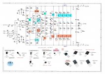
I've marked on diagram "burned 1" and "burned 2" meaning "burned 1" = what found already burned when amplifier was received, "burned 2" = what keep on burning during trial tests.
On trial test I've had weaker final transistors (2SC5198 SI-N 140V 10A 100W 30MHZ - TO3PN / 2SA1941 SI-P 140V 10A 100W 30MHZ - TO3PN instead of : MJL3281A NPN TO-264 260 V, 15 A, 200 W / MJL1302A PNP TO-264 200 V, 15 A, 200 W and also Q409 = MJE350 SI-P 300V 0.5A 20W was substituted by weaker B861 PNP -200 V -2 A max 30W) - and ONLY 2 of final transistors WERE USED , a PNP and a NPN - but based on datasheet should be working , at least for a while on ± 100V power supply.
Reason for burned2 is that potentiometers were so old that became noisy and during volume up it was a strong noise from potentiometer going to speaker - "overload" the stage - and after that R428 smoked by Q410,Q411 shorted etc .
Regarding fuses: Due amplifier is rated 2 x 600W I thing fuses should be around 6A not 10A as in diagram, no matter one MJL is max 15A.
One SC transistor is rated 10A but during trials both of them shorted altough 5A fuses not burned (to protect anything).
Burned2: Both 2SC5198 and 2SA1941 shorted between B-C not E-C
Burned2: IRF 630 shorted between G-D (10 ohms)
Burned2: IRF 9630 shorted between G-S (0 ohms)
Strange is R407 was burned1 altough Q401 ok.
Also, I think on 100V thermal heatsinks transistor silicon pads could be affected as electrical insulators.
My method was:
1. Tested idle current, DC current on ± 20V with 48V/ 20W lamps instead of fuses - ok
2. Tested idle current, DC current on ± 80V with 48V/ 20W lamps instead of fuses - ok
3. Tested idle current, DC current on ± 100V with 220V / 100W lamps instead of fuses - ok
4. Tested idle current, DC current on ± 100V with 1 A fuses - skipped
5. Tested idle current, DC current on ± 100V with 5 A fuses - ok
6. Burned on step 5 while overloaded by noise. 5 A fuses remained ok.
I ordered today the properly spare parts but - meanwhile - due that 4 x MJL3281A + 4 x MJL1302A + IRF ... etc are quite expensive , I would like to receive any suggestion in order to avoid burning them again. Thanks in advance.
Do anybody has different method to protect during trial tests a 200V powered amplifier - repaired on left channel ?
I mean everything seems fine on ± 20V, ± 30V etc. .... but on ±100V instead of burning 5A fuses (normally should be 10A fuses) , burned again final and prefinal transistors.
Idle current is normal (like in non-burned right channel) , all voltages seems the same (like in non-burned right channel), no DC on output.
I've marked on diagram "burned 1" and "burned 2" meaning "burned 1" = what found already burned when amplifier was received, "burned 2" = what keep on burning during trial tests.
On trial test I've had weaker final transistors (2SC5198 SI-N 140V 10A 100W 30MHZ - TO3PN / 2SA1941 SI-P 140V 10A 100W 30MHZ - TO3PN instead of : MJL3281A NPN TO-264 260 V, 15 A, 200 W / MJL1302A PNP TO-264 200 V, 15 A, 200 W and also Q409 = MJE350 SI-P 300V 0.5A 20W was substituted by weaker B861 PNP -200 V -2 A max 30W) - and ONLY 2 of final transistors WERE USED , a PNP and a NPN - but based on datasheet should be working , at least for a while on ± 100V power supply.
Reason for burned2 is that potentiometers were so old that became noisy and during volume up it was a strong noise from potentiometer going to speaker - "overload" the stage - and after that R428 smoked by Q410,Q411 shorted etc .
Regarding fuses: Due amplifier is rated 2 x 600W I thing fuses should be around 6A not 10A as in diagram, no matter one MJL is max 15A.
One SC transistor is rated 10A but during trials both of them shorted altough 5A fuses not burned (to protect anything).
Burned2: Both 2SC5198 and 2SA1941 shorted between B-C not E-C
Burned2: IRF 630 shorted between G-D (10 ohms)
Burned2: IRF 9630 shorted between G-S (0 ohms)
Strange is R407 was burned1 altough Q401 ok.
Also, I think on 100V thermal heatsinks transistor silicon pads could be affected as electrical insulators.
My method was:
1. Tested idle current, DC current on ± 20V with 48V/ 20W lamps instead of fuses - ok
2. Tested idle current, DC current on ± 80V with 48V/ 20W lamps instead of fuses - ok
3. Tested idle current, DC current on ± 100V with 220V / 100W lamps instead of fuses - ok
4. Tested idle current, DC current on ± 100V with 1 A fuses - skipped
5. Tested idle current, DC current on ± 100V with 5 A fuses - ok
6. Burned on step 5 while overloaded by noise. 5 A fuses remained ok.
I ordered today the properly spare parts but - meanwhile - due that 4 x MJL3281A + 4 x MJL1302A + IRF ... etc are quite expensive , I would like to receive any suggestion in order to avoid burning them again. Thanks in advance.
Attachments
...Reason for burned2 is that potentiometers were so old that became noisy and during volume up it was a strong noise from potentiometer going to speaker ...
Strong noise is a sign for oscillations. Do you have an Oscilloscope? If not, make a small detector for HF→ HF filter, rectification and a LED for display.
2SC5198 SI-N 140V 10A 100W 30MHZ - TO3PN / 2SA1941 SI-P 140V 10A 100W 30MHZ - TO3PNHelo,guys !
Do anybody has different method to protect during trial tests a 200V powered amplifier - repaired on left channel ?
I mean everything seems fine on ± 20V, ± 30V etc. .... but on ±100V instead of burning 5A fuses (normally should be 10A fuses) , burned again final and prefinal transistors.
Idle current is normal (like in non-burned right channel) , all voltages seems the same (like in non-burned right channel), no DC on output.
I've marked on diagram "burned 1" and "burned 2" meaning "burned 1" = what found already burned when amplifier was received, "burned 2" = what keep on burning during trial tests.
On trial test I've had weaker final transistors (2SC5198 SI-N 140V 10A 100W 30MHZ - TO3PN / 2SA1941 SI-P 140V 10A 100W 30MHZ - TO3PN instead of : MJL3281A NPN TO-264 260 V, 15 A, 200 W / MJL1302A PNP TO-264 200 V, 15 A, 200 W and also Q409 = MJE350 SI-P 300V 0.5A 20W was substituted by weaker B861 PNP -200 V -2 A max 30W) - and ONLY 2 of final transistors WERE USED , a PNP and a NPN - but based on datasheet should be working , at least for a while on ± 100V power supply.
Reason for burned2 is that potentiometers were so old that became noisy and during volume up it was a strong noise from potentiometer going to speaker - "overload" the stage - and after that R428 smoked by Q410,Q411 shorted etc .
Regarding fuses: Due amplifier is rated 2 x 600W I thing fuses should be around 6A not 10A as in diagram, no matter one MJL is max 15A.
One SC transistor is rated 10A but during trials both of them shorted altough 5A fuses not burned (to protect anything).
Burned2: Both 2SC5198 and 2SA1941 shorted between B-C not E-C
Burned2: IRF 630 shorted between G-D (10 ohms)
Burned2: IRF 9630 shorted between G-S (0 ohms)
Strange is R407 was burned1 altough Q401 ok.
Also, I think on 100V thermal heatsinks transistor silicon pads could be affected as electrical insulators.
My method was:
1. Tested idle current, DC current on ± 20V with 48V/ 20W lamps instead of fuses - ok
2. Tested idle current, DC current on ± 80V with 48V/ 20W lamps instead of fuses - ok
3. Tested idle current, DC current on ± 100V with 220V / 100W lamps instead of fuses - ok
4. Tested idle current, DC current on ± 100V with 1 A fuses - skipped
5. Tested idle current, DC current on ± 100V with 5 A fuses - ok
6. Burned on step 5 while overloaded by noise. 5 A fuses remained ok.
I ordered today the properly spare parts but - meanwhile - due that 4 x MJL3281A + 4 x MJL1302A + IRF ... etc are quite expensive , I would like to receive any suggestion in order to avoid burning them again. Thanks in advance.
It is not Power Final Transistor , it is a prefinal transistor 🙂 !
100V rails is CRAZY.
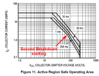
In power amp design, maximum rated voltage by itself is irrelevant ; what DESTROYS Bipolar power transistors is Second Breakdown .... which you are recklessly surpassing, and it brings instant karma: transistor destruction.
I´m attaching below the relevant second breakdown graph.
Yes, it shows transistors reaching 200V+ ... but look at the permissible current: ridiculous 150mA.
Even if you short amp output, so transistor will handle just *one* rail, protection circuit must limit current to 1A .... a heavy task which will require > 0.7 ohm emitter resistors and at least doubling of power devices, so AT LEAST 8 output pairs, 16 transistors in total.
And even so ... you have already started second breakdown which is a self accelerated destruction mechanism.
Somebody said (accurately) that "second breakdown is the method by which 250W lions turn into 50W kittens"
Look at the graph I attach below: permissible dissipation curves start to kink DOWN between 70V and 80V , showing the second breakdown start.
I would NOT use that amp with higher than +/-70V rails ... PERIOD.
That it works at the Lab (you tested it with +/- 80V rails) does not mean it will be reliable or survive for long in the real World.
Protection in that schematic shows that under short condition, transistors are subject to rail voltage and 2A current limiting ... which graph shows is "acceptable" up to 70 Vce ... and that for 1 second ... long enough for *another* protection circuit to open a speaker out relay or mute input.
A second confirmation that you must not use that amp with more than +/-70V rails.
Attachments
MJL21195-D.pdf | DocDroid
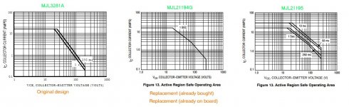
Only this variant is the correct one, being the original one, not the one from the service scheme
Check the SOA chart 😉 !
Only this variant is the correct one, being the original one, not the one from the service scheme
Check the SOA chart 😉 !
Strong noise is a sign for oscillations. Do you have an Oscilloscope? If not, make a small detector for HF→ HF filter, rectification and a LED for display.
Could be crossover distortion ?????
I've replaced everything burned left channel a/p factory initial values , everything seems now ok but very slight distorsion at low level. If increased , no distorsion.
Still on trial , for the moment I am afraid to raise the power. On trial +- 50V, seems ok.
Interesting ideea for HF detector !
No scope, it is realiable one based on PC sound card ?...
2SC5198 SI-N 140V 10A 100W 30MHZ - TO3PN / 2SA1941 SI-P 140V 10A 100W 30MHZ - TO3PN
It is not Power Final Transistor , it is a prefinal transistor 🙂 !
I agree, my fault, in a hurry I've tested by unfitted components.
100V rails is CRAZY.
In power amp design, maximum rated voltage by itself is irrelevant ; what DESTROYS Bipolar power transistors is Second Breakdown .... which you are recklessly surpassing, and it brings instant karma: transistor destruction.
I´m attaching below the relevant second breakdown graph.
Yes, it shows transistors reaching 200V+ ... but look at the permissible current: ridiculous 150mA.
Even if you short amp output, so transistor will handle just *one* rail, protection circuit must limit current to 1A .... a heavy task which will require > 0.7 ohm emitter resistors and at least doubling of power devices, so AT LEAST 8 output pairs, 16 transistors in total.
And even so ... you have already started second breakdown which is a self accelerated destruction mechanism.
Somebody said (accurately) that "second breakdown is the method by which 250W lions turn into 50W kittens"
Look at the graph I attach below: permissible dissipation curves start to kink DOWN between 70V and 80V , showing the second breakdown start.
I would NOT use that amp with higher than +/-70V rails ... PERIOD.
That it works at the Lab (you tested it with +/- 80V rails) does not mean it will be reliable or survive for long in the real World.
Protection in that schematic shows that under short condition, transistors are subject to rail voltage and 2A current limiting ... which graph shows is "acceptable" up to 70 Vce ... and that for 1 second ... long enough for *another* protection circuit to open a speaker out relay or mute input.
A second confirmation that you must not use that amp with more than +/-70V rails.
I fully agree with you. Unfortunatelly I can not replace the power transformer.
I've tested the amp and seems stable on +- 80V. I am afraid to raise on +-100V. Still on trial ... Nest step is to raise the voltage and check the currents with 100 ohms load
MJL21195-D.pdf | DocDroid
Only this variant is the correct one, being the original one, not the one from the service scheme
Check the SOA chart 😉 !
But the right channel still working - it has been working 30 years - with weak MLJ:
MJL3281A NPN TO-264 260 V, 15 A, 200 W
MJL1302A PNP TO-264 200 V, 15 A, 200 W (original ones on right channel that is not touched)
I bought and implanted already MJL
MJL21194G NPN 250V 16A 200W TO264
MJL21193G PNP 250V 16A 200W TO264
I did not know about MJL21195....
Anyway I have some crossover distorsion , I think, and is around Q404 due on left bad channel voltages are less by half volt comparative to good right channel.
This distorsions sound like a wrong bias ... Only an low level
(Google translate, sorry , no time today to edit directly in English...)
Today we tested the problem channel with the new components:
1b. load 100 + 8 ohms, ± 100V with 47 ohms instead of fuses - ok
2b. load 100 + 8 ohms, ± 100V with 20 ohms instead of fuses - ok
3b. 100 + 8 ohm load, ± 100V with 1.5 A fuses - ok
5b. 24V / 50W + 8 ohm bulb load, ± 100V with 1.5 A fuses - ok
I am going to put all the ends and I will go directly with 100W bulbs instead of fuses, then 5b, then 8A fuses directly with the 8 ohm load and that will be ...
MJL21194G NPN 250V 16A 200W TO264
MJL21193G PNP 250V 16A 200W TO264
from Mivarom, I was warned that it might be off-specs but I am optimistic.
My reservation is related to the following:
R1. At 600W / channel the fuses should be 6-7 A instead of 10A as they are on the manufacturer's diagram, otherwise they are useless
R2. SOA for MJL3281A and MJL1302A - on the original diagram - together with the protection on a single emitter leads to catastrophe in case of overload
R3. Protection on a single emitter, on the resistance of 0.33 ohms (just like the others that are not protected) leads to another catastrophe because the transistors are expensive and you can't buy 20 and out of 20 to pair 8
R4. Under the above conditions the scheme seems stable for ± 70V ... ± 80V, not for ± 100V as designed
R5. At ± 100V it would be reasonable not to lower the 8 ohm sound. There are no manufacturer specifications.
I'll be back after all the finals onboard.
- Home
- Amplifiers
- Solid State
- Method to protect a MOS-FET->BIPOLAR 200V powered amplifier during tests