Hi All!
I'm designing the metal box for my project, (analog design) and now i am designing the apertures for ventilation on the top cover.
I follow patterns i see out there, and some rules of thumb proposed on several papers.
The pattern i made is two vertical rows of rectangular apertures with the following dimensions:
Aperture dimensions: 1,9mm height. 15,1mm length. diagonal: 15.2mm
Distance between columns: 6.4mm
Distance between rows: 4mm
Total rows : 24. The idea with these apertture dimensions is to attenuate somewhat (-20db) at 1ghz... 😛 to stop the RFi coming IN.
I just want to know if i am on the right track...despite i think this is a try and fail process... ;D
Another question that worries me is the front panel aperture for AC rocker switch...(a typical dpst squared plastic model) is the aperture a way for RFI getting in the box..?? maybe not...or maybe i'm worrying too much...😱
Thank you for your advise!
jay x
To be certain you would have to do a full EM wave simulation. However, your hole sizes are small compared to a wavelength at 1GHz (30cm) so I would expect significant attenuation. 15mm is 10% of half a wavelength so you may get some penetration. Two 7.5mm slots may be better than one 15mm slot.
One thing to watch out for is the edge where one panel meets another. If an edge is somewhere around 15cm in length between fixings then you could get extremely good RF penetration as you have created a slot scatterer for 1GHz!
One thing to watch out for is the edge where one panel meets another. If an edge is somewhere around 15cm in length between fixings then you could get extremely good RF penetration as you have created a slot scatterer for 1GHz!
Hi DF!
Thanks for your advise!!
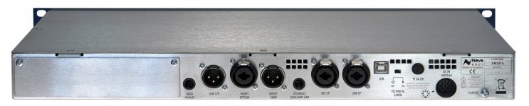
The top cover in my design meets the case more or less like in the picture attached.. it is a flat metal sheet, so i have to assure the top cover makes good contact with the case at smaller intervals than 15cm, like 10 or 7,5cm... the depth of my case is about 185mm.
jay x
Thanks for your advise!!
The top cover in my design meets the case more or less like in the picture attached.. it is a flat metal sheet, so i have to assure the top cover makes good contact with the case at smaller intervals than 15cm, like 10 or 7,5cm... the depth of my case is about 185mm.
jay x
Attachments
If you are serious about keeping 1GHz out then you need fixings a lot closer than 7.5cm. RF gaskets have contacts every few mm. Alternatively, accept that some RF will get in and ensure that the circuit inside will ignore it.
open up an old TV tuner or a mobile phone.
You will see in there little RF attenuation tin plated steel boxes . They are either soldered closed, or have many fingers, creating electrical contact every few mm around the whole perimeter of the seam.
Look at the back of your PC interface plate. All the little boxes penetrating the plate have contact fingers to ensure short gaps between electrical contacts.
Your cover plate on the back breaks all the rules for RF attenuation.
The socket holes also let in RF if the other side has any electrical gaps to the chassis.
Last edited:
1. You have wires going into the box...no shielding there...antenna on the outside and antenna on the inside. You would need a filtered connector to maintain shielding for all conductive paths. Look up 56F715-005 in Mouser or Newark for an example.
2. The aluminum is probably raw or anodized. Not good contact unless "oriented wire" gasket is used between surfaces. http://www.shielding.com/2. Oriented Wire Shield and Seal.htm This type of gasket breaks the aluminum oxide (insulator) layer that forms within a few seconds of oxygen exposure. Specific coatings can be used to keep the surface conductive. https://en.wikipedia.org/wiki/Chromate_conversion_coating You still need a gasket material between surfaces.
3. Look at a microwave oven door. There are a large quantity of holes...scale these hole sized based on the frequency (or wavelength) of the microwave oven.
https://en.wikipedia.org/wiki/Microwave_oven Or find calculations for slots on EMI/EMC shielding related websites...Had a book but it is packed in a box somewhere.
4. A better way for switches would to be use a insulated rotary or push-on-off switch. Use an insulated shaft through a holes that forms a "waveguide beyond cuttoff" ( calculator here: http://www.wa1mba.org/WGCalc.htm )
Last edited:
- Status
- Not open for further replies.