I have been working with the Beyma 750Ti CD for some time. It is a great performer with an extended HF, well built and sensibly priced. I have coupled it to a few horns but for these tests ran with the P Audio PH 4525, which is identical to the Goldwood version. These horns are 2380a derivatives but with a circular throat section coupled to the diffraction slot negating some of the criticisms levelled at the JBL 80's designs.
But I have always been a believer in consistent and maximum damping of any driver being basically "a good thing". I set about creating an RCL circuit to maintain a level impedance and negligible change in the phase angle of the impedance.
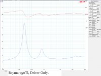
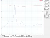
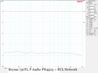
With DATs to hand I ran impedance and phase plots of driver only, driver + horn and driver + horn + RCL network. The results were, IMO, interesting. The driver only has an Fs of 660Hz rising to 907Hz when loaded to the horn. With the RCL in circuit DAT's suggested a figure of 444Hz but I suspect it was confused by the flat impedance?
What about the sound? Measuring FR and waterfalls with ARTA proves that parallel components such as an RCl have negligible impact on measured FR. It did reveal a marginal increase in LF extension with the RCL in circuit but what I wasn't expecting was a quite clear difference in sound quality. IMO the RCL version sounded less like a horn with more solid imaging and less "phasey"..if that's a word!
Sticking with the science rather than the snake oil, I can't help thinking there must be benefits to having maximum damping from your amplifiers and the "flat lining" phase of the impedance can't be a bad thing either?
And although not an advocate of passive crossovers, this impedance levelling must be a dream....🙂
Anyway, here are the plots...comments welcome!
But I have always been a believer in consistent and maximum damping of any driver being basically "a good thing". I set about creating an RCL circuit to maintain a level impedance and negligible change in the phase angle of the impedance.
With DATs to hand I ran impedance and phase plots of driver only, driver + horn and driver + horn + RCL network. The results were, IMO, interesting. The driver only has an Fs of 660Hz rising to 907Hz when loaded to the horn. With the RCL in circuit DAT's suggested a figure of 444Hz but I suspect it was confused by the flat impedance?
What about the sound? Measuring FR and waterfalls with ARTA proves that parallel components such as an RCl have negligible impact on measured FR. It did reveal a marginal increase in LF extension with the RCL in circuit but what I wasn't expecting was a quite clear difference in sound quality. IMO the RCL version sounded less like a horn with more solid imaging and less "phasey"..if that's a word!
Sticking with the science rather than the snake oil, I can't help thinking there must be benefits to having maximum damping from your amplifiers and the "flat lining" phase of the impedance can't be a bad thing either?
And although not an advocate of passive crossovers, this impedance levelling must be a dream....🙂
Anyway, here are the plots...comments welcome!
Attachments
RCL Network
Hi,
It wasn't my intention to give away hours of work but to gather comments as to the veracity of the research. But I'll post it anyway!
A RCL network is a circuit of series components in parallel with the load. (Resister+Choke+Capacitor) to level the impedance spikes (as you probably know) and as seen in the plots. A simple zobel, (Resister + Capacitor) was implemented to flatten the rising impedance with frequency, working substantially well up to 10KHz (see plot). I only ran the DATs signal generator from around 200Hz to 20KHz because obviously one would not use this horn combination below 500Hz and preferably higher. I find around 680Hz with a 24dB/octave DSP filter suits them well....
There may be simpler or more elegant circuits but I was happy with the results having achieved an impedance across the whole usable frequency range of around +/- .5 Ohm!
Attachments
without knowing how you've accomplished this it would be hard to replicate it to evaluate the effect with other horns and whether or not it makes an audible improvement....
oops.... now that i've looked at the file you've attached i see what you've done.
oops.... now that i've looked at the file you've attached i see what you've done.
Last edited:
How did you evaluate the sound? Did you connect the driver directly to the amplifier or was there some form of crossover in between?
DATs doesn't require an amp. Its usb connected to your computer which has preloaded software. DATS sends out a pulse and creates the plots. I have shown three plots...driver impedance only, driver mounted to horn and driver, horn and rcl.
No passive crossover is connected as this would impact on the result. What we are looking at here is just the load an amp would see. I don't use passive anyway but the calculation would be simple given such a flat impedance?
No passive crossover is connected as this would impact on the result. What we are looking at here is just the load an amp would see. I don't use passive anyway but the calculation would be simple given such a flat impedance?
still trying to analyze what you've done.
it appears to be three notches and a low pass?
all to flatten the impedance curve...
only penalty i can see with doing this would be the insertion loss.
it appears to be three notches and a low pass?
all to flatten the impedance curve...
only penalty i can see with doing this would be the insertion loss.
- Status
- Not open for further replies.
- Home
- Live Sound
- PA Systems
- Messing with RCL's