Greetings, been a while since I posted.
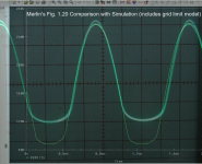
Still pondering about triode grid current limiting and the resulting plate wave form negative swing limit, I decided to try to match up Merlin's Fig. 1.20 in his excellent book "Designing Tube Preamps for Guitar and Bass" with my PSpice simulation using the Ayumi and Wayne Clay (curve captor) 12AX7A spice models. I have overlaid the two scope shots as best I could. Not perfect but good enough to see that the lower limits differ quite a bit. If there is any merit to my method, then the SPICE model limits at about 88V, while Merlin's test scope shot indicates the lower limit is close to 120V. Is either voltage realistic?
I asked ChatGPT o1 to deep think about this and present the commonly-reported lower limits it could find, and it came up with 40-60V (Rp=100k, Rk=1k5).
See the attached overlay (@Merlinb, hopefully you are ok with me posting this publicly-available scope shot from your book).
Attachments
Last edited:
That negative swing is really the positive limit of swing of the grid voltage. That's gonna depend on the grid-current in the tube / model, which is notoriously variable. Most tube models don't include grid current at all, does yours?

Indeed the output wave form is an indication of positive grid current limiting, and yes the SPICE model's output shown superimposed on top of your actual scope shot is with a grid current model implemented.That negative swing is really the positive limit of swing of the grid voltage. That's gonna depend on the grid-current in the tube / model, which is notoriously variable. Most tube models don't include grid current at all, does yours?
Comparing the two resulting lower limits, it would appear the spice grid model is incorrect, would you agree?
Is my blended scope shot accurately indicating what your circuit was limiting at when you performed the test (i.e. 120V)?
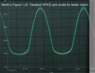
I decided to take the existing grid current model (part of Charles Rydel's complete model) as shown in the first post, and tweak it to see if I can match the grid current limiting as shown in your Fig 1.20. The only minor deficiency with Rydel's grid current model is that the threshold of grid conduction was fixed at 0V Vgk with no apparent means to set it to some negative value. I managed to introduce another parameter that allows for negative conduction thresholds. In this case I adjusted that to -0.65V.
In my opinion this has achieved a fairly good plate wave form match. See attachment. More testing will follow.
In my opinion this has achieved a fairly good plate wave form match. See attachment. More testing will follow.
Attachments
For completeness, here is the overlay of Merlin's scope shot and the SPICE simulation, but this time with the grid current model removed. This provides an eye-opener in terms of how much limiting this particular circuit exhibits. Vin is 2Vp.
The unencumbered (no grid model) voltage swing is about 200Vpp, while the total swing with the grid model is only about 130Vpp. About 35% of the bottom portion of the wave form is clipped.
The unencumbered (no grid model) voltage swing is about 200Vpp, while the total swing with the grid model is only about 130Vpp. About 35% of the bottom portion of the wave form is clipped.
Attachments

Well that certainly explains a lotThe only minor deficiency with Rydel's grid current model is that the threshold of grid conduction was fixed at 0V Vgk with no apparent means to set it to some negative value. I managed to introduce another parameter that allows for negative conduction thresholds. In this case I adjusted that to -0.65V.
- Home
- Amplifiers
- Tubes / Valves
- Merlin's Fig. 1.20